External fixation assembly and method of use

a technology of fixing pins and fixing rods, applied in the field of external fixation, can solve the problems of aggravated patient's condition, infection of the pin tract in the bone, delay in patient recovery, etc., and achieve the effect of reducing pressure, reducing inflammation and infection, and reducing pressur

Inactive Publication Date: 2008-11-13
WAKE FOREST UNIV HEALTH SCI INC
View PDF99 Cites 13 Cited by
  • Summary
  • Abstract
  • Description
  • Claims
  • Application Information

AI Technical Summary

Benefits of technology

[0004]Based on the foregoing, an external fixation assembly includes a plurality of hollow fixator pins for insertion into a patient's bone. Each pin has a hollow shaft with an insertion end that may be advanced through a tissue opening and into the patient's bone. The shaft has an interior passageway or conduit such as a bore that extends generally along the longitudinal axis of the shaft. At least one vent aperture, and optionally a plurality of v

Problems solved by technology

Long term use of external fixator pins involves risks and complications that can delay the patient's recovery and further aggravate the patient's condition.
In some patients, the pin may resul

Method used


Image

  • External fixation assembly and method of use
  • External fixation assembly and method of use
  • External fixation assembly and method of use

Examples


second embodiment

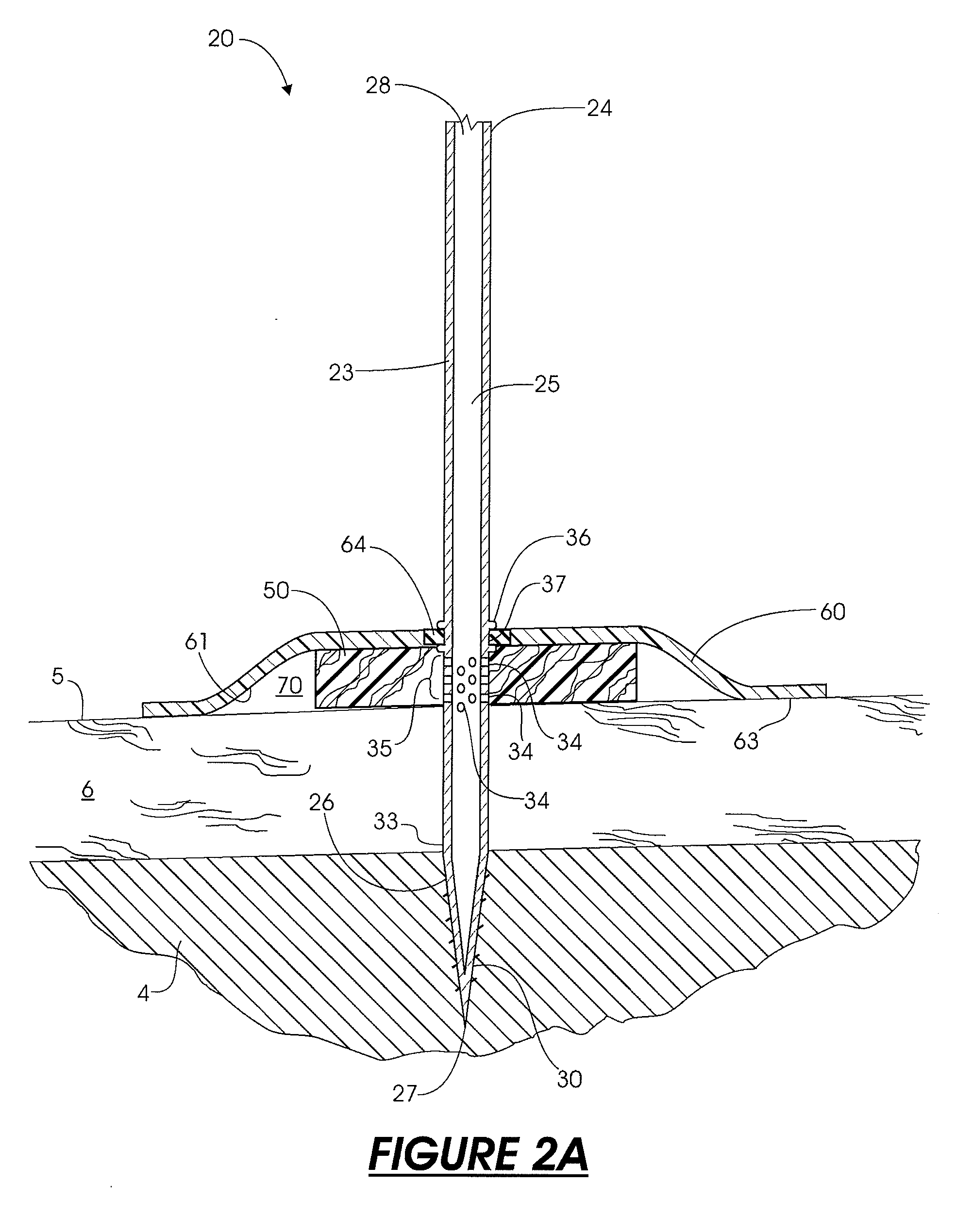
[0027]Returning now to FIG. 2A, a plurality of apertures 34 may be formed through the non-threaded section 33 of the shaft 23 to form a vent section 35 along the length of the shaft. The apertures 34 extend through the wall of the shaft 23. When the vacuum pump 12 is activated, the vacuum pump draws air or gas through the apertures 34 to create negative pressure through and along the apertures. The apertures 34 may be positioned at various locations relative to the tip 27 to apply reduced pressure at specific areas within the pin tract. For example, the apertures 34 may be positioned where the pin intersects with the epidermis 5 (“skin / pin interface”), as shown in FIG. 2. In this arrangement, the apertures may form a vent section 35 at a location at and above the epidermis to supply negative pressure through a reduced-pressure distribution element or screen 50. Alternatively, the apertures 34 may be positioned where the pin intersects deeper tissue layers in the dermis 6. Apertures ...

third embodiment

[0035]Referring now more specifically to FIG. 3, a fixator pin 120 is shown. The fixator pin 120 is configured to apply reduced pressure at the bone / pin interface in a pin tract. The fixator pin 120 is substantially similar to the pins described above, having a hollow shaft 131 with a central bore 125, an insertion end 126, a threaded section 130 on the insertion end, a non-threaded section 133, and a plurality of apertures 134. The apertures 134 are formed in the threaded section 130 of the insertion end 126 as opposed to the non-threaded section 133 of the shaft. In this way, the reduced pressure is applied through bore 125 to the pin tract inside the bone 4. Referring to FIG. 4, the apertures 134 are preferably recessed in the groove formed by the thread on the threaded section at the tip 137. The groove provides additional void space around the apertures to reduce the potential for clogging caused by bone fragments that may become lodged in the apertures.

fourth embodiment

[0036]In some cases, it may be desirable to locate the vacuum port as a side port on the side of the pin, rather than at the attachment end. For example, the fixator appliance may have retainers that connect over the top of the fixator pins, covering the attachment ends of the pins and preventing connection of flexible tubing to the attachment ends. Therefore, locating the vacuum port on the side of the pin can avoid problems that occur when the attachment end is obstructed or inaccessible. In FIG. 5, a fixator pin 220 is shown in accordance with the invention. The fixator pin 220 is connected to a retainer 221 that covers the end of the fixator pin. A vacuum port 228 is formed through the side wall of the pin 220 and connects with a flexible tube 214. A cylindrical hub 229 surrounds the vacuum port 228 and projects radially outwardly from the side wall of the pin 220. The flexible tube 214 is adapted to slide over the hub 229 to connect the port 228 to a vacuum pump or other source...


PUM


Abstract

An external fixation assembly includes a plurality of hollow pins that are inserted into a patient's bone. Each pin has an interior bore and a plurality of apertures extending through the pin wall from the bore. The pin may be coupled to a source of vacuum pressure operable to create reduced pressure in the tissue surrounding the pin. A cover is placed around the pin and sealed to provide a fluid-tight enclosure that maintains reduced pressure around the pin. A method for applying external fixation using the fixator pins described above includes the steps of inserting each pin through a skin opening, positioning the pin apertures near selected tissue, covering the skin opening with a sealed enclosure, connecting the pins to a source of vacuum pressure, and activating the source of vacuum pressure to create reduced pressure in the patient's tissue at or near the bone.

Description

RELATED APPLICATIONS[0001]This application claims the benefit of priority of U.S. Provisional Application No. 60 / 866,327, filed on Nov. 17, 2006, the entire contents of which application are incorporated herein by reference.FIELD OF THE INVENTION[0002]The present invention relates to external fixation, and particularly to fixator pins and devices used in treating bone fractures and deformities with the use of sub-atmospheric pressure.BACKGROUND[0003]External fixation is a common technique used to treat a variety of conditions, including bone fractures, dislocations, and deformities. Although different techniques are used, external fixation generally involves the use of threaded fixator pins that are screwed into bone. For bone fractures, two or more fixator pins are inserted into the bone on each side of the fracture. Compression and distraction forces are applied to the fixator pins to correctly position and align the bone. External fixation may be applied over several months for c...

Claims


Application Information

Patent Timeline
IPC IPC(8): A61B17/00A61B17/60
CPCA61B17/60A61B17/66A61B2017/00544A61B17/866A61B17/8685A61B17/864
Inventor WEBB, LAWRENCE X.ARGENTA, LOUIS C.MORYKWAS, MICHAEL J.
Owner WAKE FOREST UNIV HEALTH SCI INC
Why Eureka
Try Eureka