[0010]In one form of this invention there is provided a connecting rod for an
internal combustion engine including a hollow beam member. The hollow beam connecting rod includes a
piston pin bearing boss and
crankshaft bearing boss elements. The boss elements are typical for high performance “racing” engine requirements that have configuration eliminating
stress concentration, and providing force flux pathways to minimize stress levels and provision for high strength
alloy steel, features generally lacking in prior art. The first end of the improved hollow beam member is joined to a high performance
piston pin bearing boss element through a first curved region. The second end of the hollow beam member is joined to a high performance
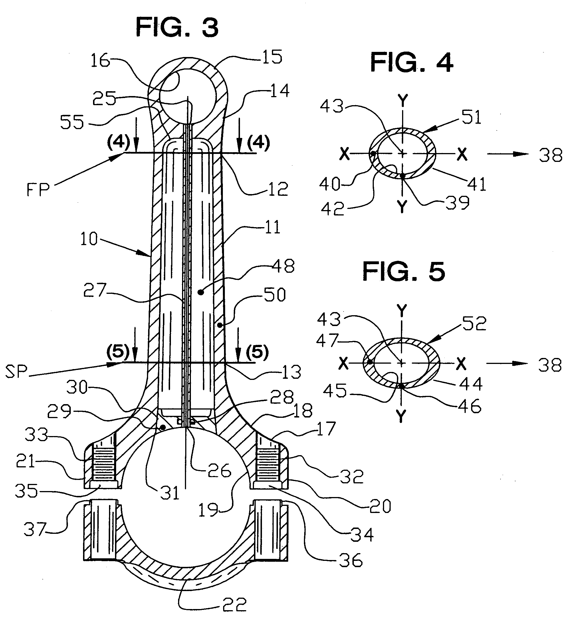
crankshaft bearing boss through a second curved region. The primary improvement is a hollow beam member formed by projected elliptical profile cross-sections on projection planes located at the beam member first end and the second end and centered on the longitudinal beam axis. The walls of the hollow beam member are defined preferably by elliptical outer and defined inner cross-section profiles inline, projecting direct “straight” beam walls from the first to the second elliptical cross-section projective plane. Avoiding the tangent beam sidewalls of Volkel. Sidewalls have a minimal required thickness and cross-section length increase in the major axis direction (direction of
crankshaft rotation) than in the
minor axis direction. Profiles embody a disclosed “ratio”
system specifying wall thickness and profile cross-section
major and minor axis length. In another form of the
ellipse a “prolonged
ellipse” also known as a “stretched
ellipse” is provided by increasing the eccentricity (length) in the major axis.
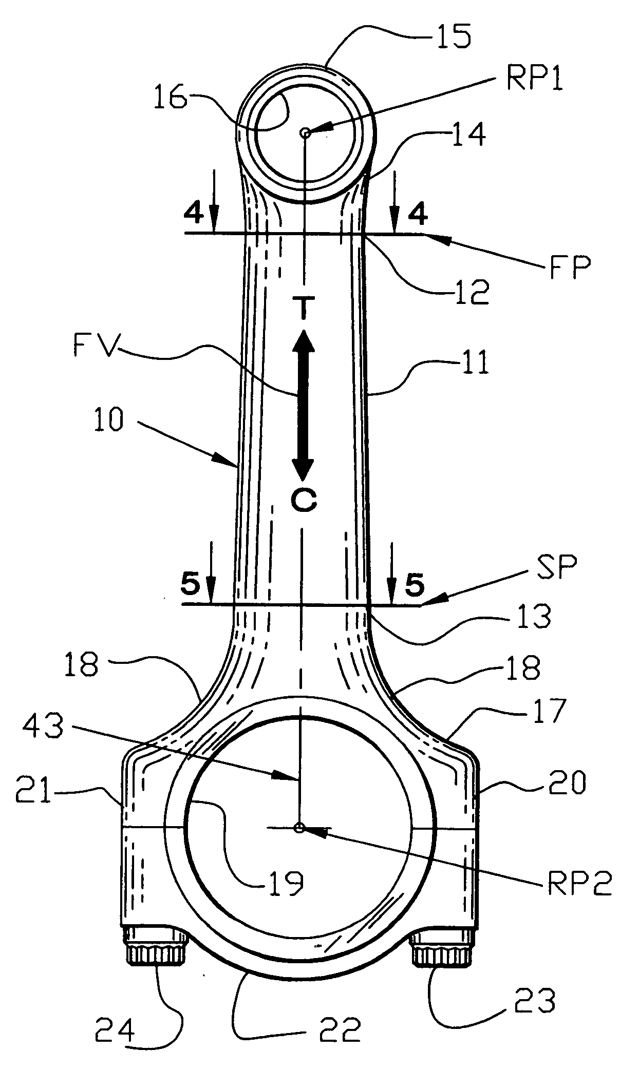
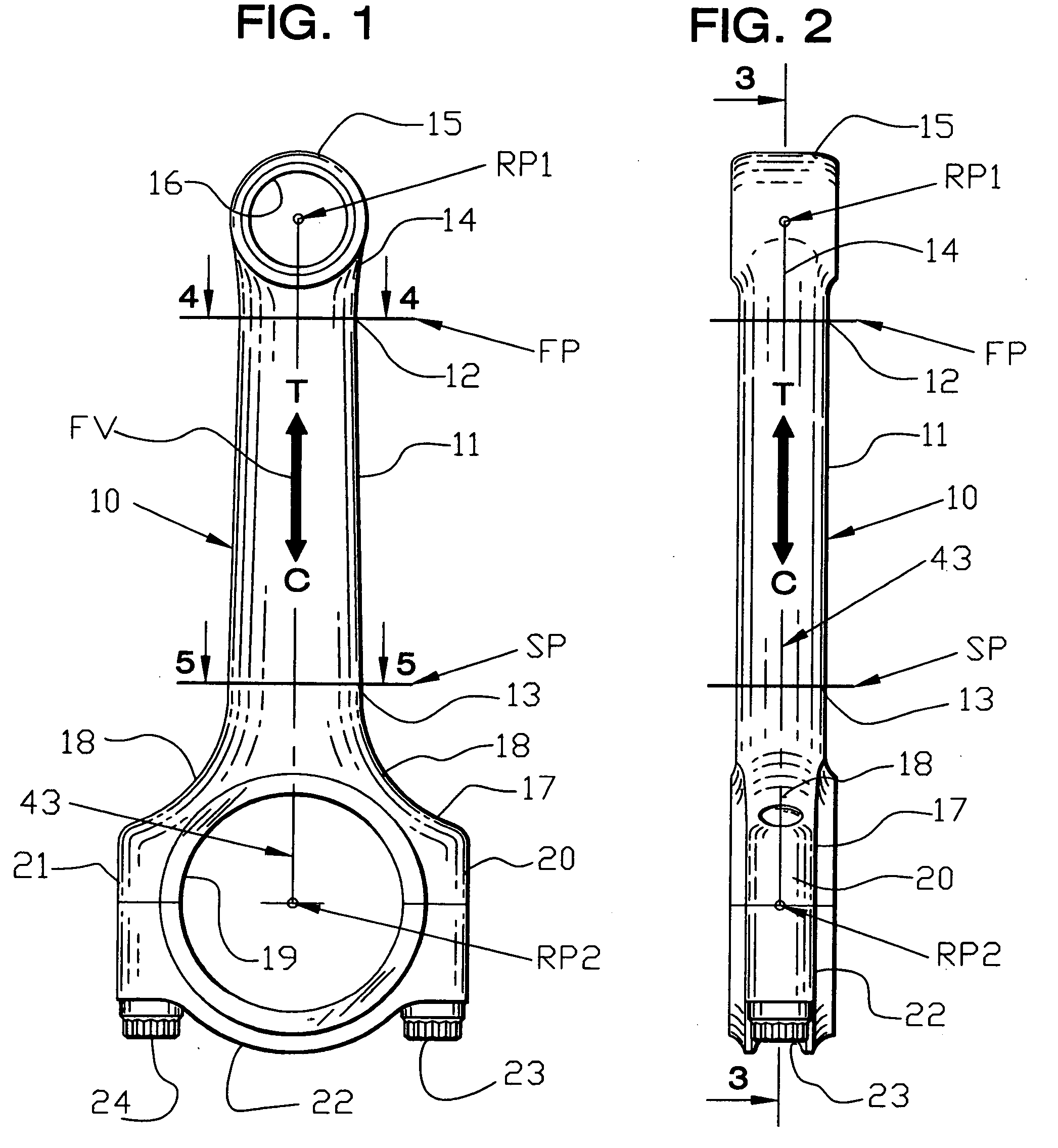
[0012]The present invention provides a connecting rod comprising a hollow beam member of near minimum cross-section area and
mass achievable. It is preferred that this is accomplished by precise beam wall cross-sections having elliptical or convex segment cross-section profile formation configured to a beam member
column structure, having specific profile sidewall thickness and width ratios. The disclosed
beam column form directs compressive and tensile forces centered about the longitudinal axis of
load force path from
piston pin to crankshaft journal, improving and “keeping the load path inline” and in-close proximity to the longitudinal axis. Thus efficiently distributing
stress concentration throughout the connecting rod beam member. The embodiment potential is
elimination or minimizing stress concentrations thus lowering
high peak stress levels. Resulting in reliable performance at high engine RPM (
Revolutions Per Minute) and improved fatigue life. This is important over prior art because weight reduction reduces
mass inertia forces further lowering stress levels. Placement of beam defining cross-sections and section profile are defined with a
ratio method to facilitate design and analysis of hollow beam connecting rod manufacturing. Materials, especially high strength
alloy steel and forgings (180,000 to 220,000 psi) are “required” for the high performance engine connecting rod embodiments of the present invention. This requirement is not provided by noted prior art; being
casting and sheet stock construction.
[0013]The primary objective of providing lower stress levels and lower reciprocating weight is to reduce
inertia forces.
Inertia forces affect engine performance and increase stress in connecting rods. Hollow rod beam weight reductions of 45 to 60 grams over competing
solid beam connecting rods have occurred in designs disclosed herein. Reduction of 45 grams of reciprocating weight will reduce peak
inertia force by about 400 pounds at peak RPM, determined in studies. Performance is improved by increasing compressive force by 400 pounds on the piston during the
power stroke. This is possible because
inertia force (400 lbs.) must be overcome during the early part of
power stroke by
combustion pressure to push the piston during the
power stroke. Thus imparting 400 lbs.
gain in force to crankshaft rotation, a performance
gain provided over prior art.
[0014]Another objective is to provide an aerodynamic shape to reduce effects of rod contact with the ambient oil particle environment and air occurring within an engine at high RPM.
[0016]An improvement of one embodiment of this invention is having a procedural embodiment to define and locate profile cross-section forms on projection planes centered on the beam longitudinal axis to project the connecting rod beam member surface form. A further purpose is to reduce the number of elements required to define a connecting rod beam to a few cross-section profiles, preferably two profiles placed on the beam longitudinal axis. The beam form disclosed using projection planes particularly facilitates connecting rod design using computer programs. This objective simplifies and facilitates accurate and analyzed connecting rod design. Computer programs which may be used are
Computer Aided Design (CAD), Finite
Element Analysis (FEA) and Computer Numerical Controlled (CNC)
machining. Another
advantage of the improvements disclosed and claimed herein is facilitated design and files computer generated and transferred by electronic means such as E-mail directly to CNC manufacturing machines and facilities.

