
Water jet cutting method

a cutting method and water jet technology, applied in the direction of basic electric elements, metal working apparatus, electric devices, etc., can solve the problem that the primary cut area is not always supported at the one end, and achieve the effect of efficiently cutting the workpiece with the desired accuracy and suppressing various cutting troubles

Inactive Publication Date: 2008-11-20
DISCO CORP
View PDF3 Cites 15 Cited by
  • Summary
  • Abstract
  • Description
  • Claims
  • Application Information

AI Technical Summary

Benefits of technology

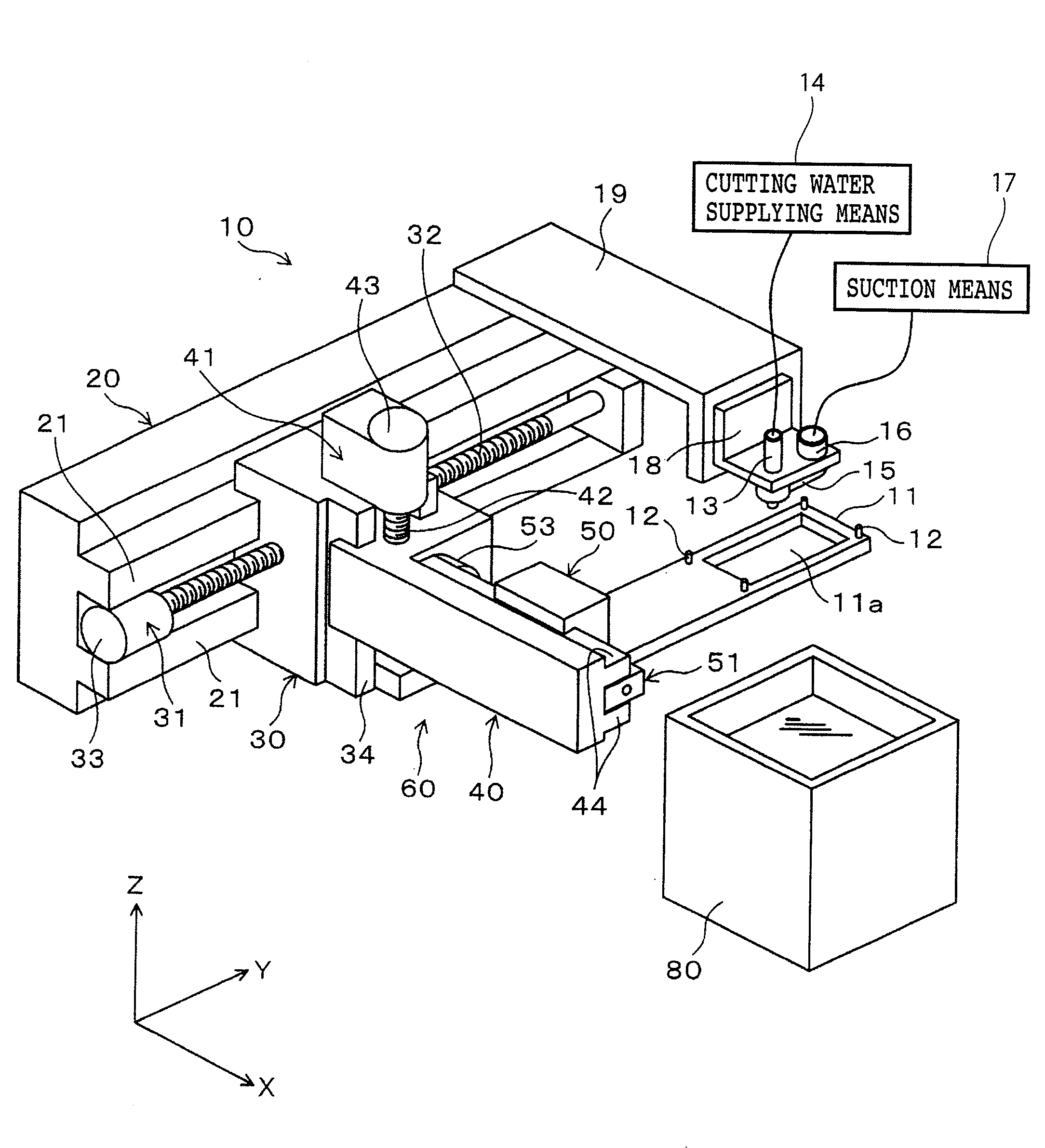
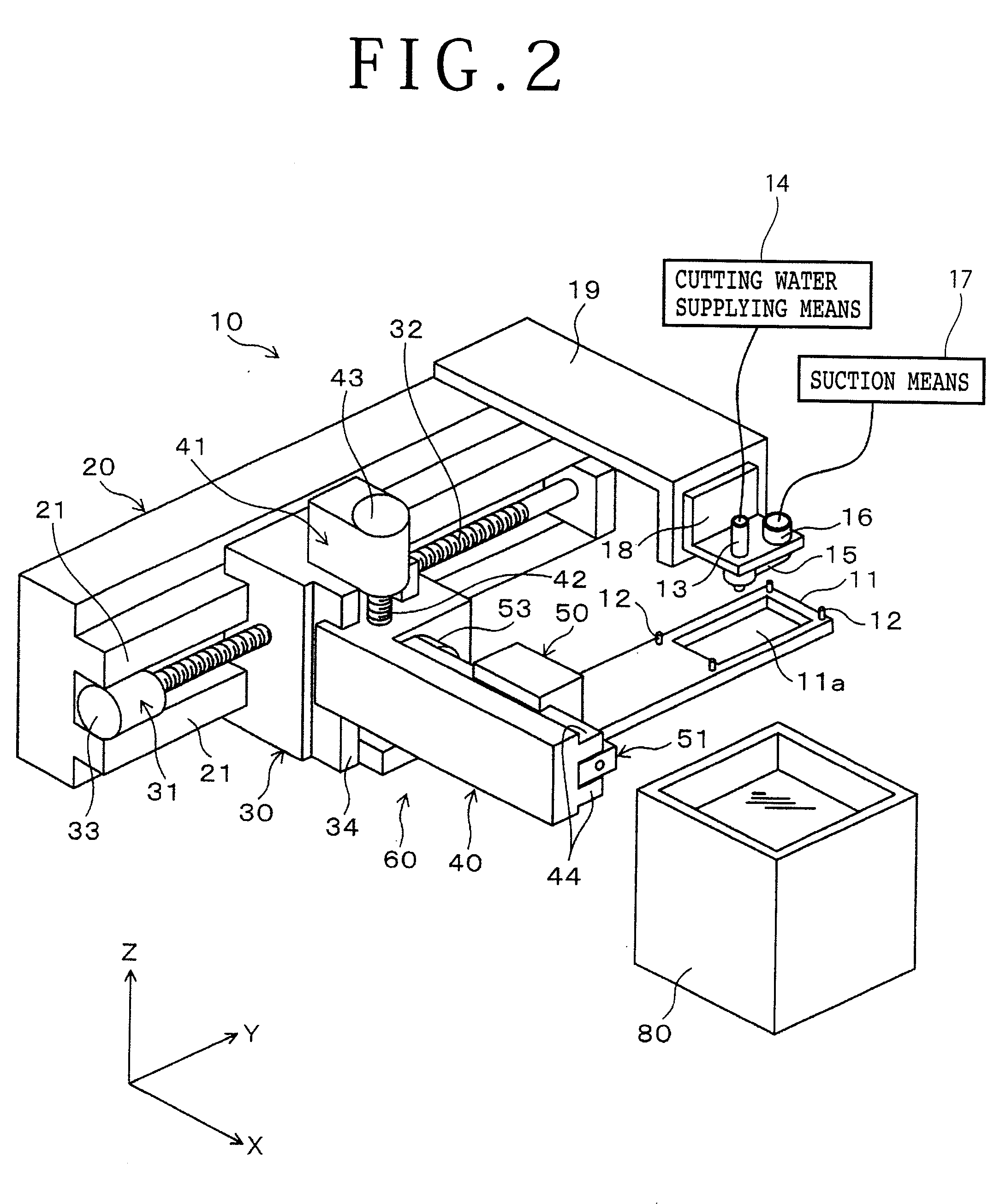
[0008]It is therefore an object of the present invention to provide a water jet cutting method for cutting a workpiece such as a substrate by using a water jet cutting device which can suppress various troubles in cutting the workpiece and can efficiently cut the workpiece with a desired accuracy.
[0010]The cutting method of the present invention includes the primary cutting step and the secondary cutting step to be separately performed. Between the primary cutting step and the secondary cutting step, the adhesive member attaching step is performed to attach the adhesive member to one side surface of the workpiece in order to prevent scattering of the individual portions of the workpiece after the secondary cutting step. In the primary cutting step, the workpiece is cut along the first group of the cutting lines to obtain the plural primary cut areas having the same shape and size in the condition that at least one end of each primary cut area is integrally supported to the workpiece. Accordingly, unlike the prior art, each primary cut area is not always supported at its one end. In other words, each cut area is supported at its opposite ends or at its one end. Even in the latter case, the length of each primary cut area supported at its one end can be made relatively small. As a result, the degree of warping and projection of each cut area of the workpiece can be suppressed.
[0011]After the primary cutting step, the adhesive member attaching step is performed to attach the adhesive member to one side surface of the workpiece. After the adhesive member attaching step, the secondary cutting step is performed to cut the workpiece along the other group of the cutting lines to obtain the plural partitioned portions having the same shape and size. Accordingly, it is possible to prevent the occurrence of various troubles after the primary cutting step, such as an error in attaching the adhesive member to the workpiece in the adhesive member attaching step. As a result, the secondary cutting step can be smoothly performed to improve the accuracy of the partitioned portions finally obtained by this cutting method.
[0012]Preferably, the cutting along the cutting lines in the primary cutting step and / or the secondary cutting step is performed continuously over at least two of the plural partitioned portions. In this case, the time for stopping the supply of the cutting water during cutting of the workpiece can be reduced, so that the overall cutting operation time can be reduced to thereby make the cutting operation more efficient.
[0013]Preferably, the cutting start and stop points of each cutting line in the primary cutting step and / or the secondary cutting step are set outside of a cutting area defined by the outermost ones of the plural cutting lines. In cutting the workpiece by using the water jet cutting device, the cutting water contains abrasive powder, so that there is a possibility of erosion on the surface of the workpiece subject to the jet of the cutting water. That is, when the jet of the cutting water containing abrasive powder is directed onto the workpiece, the cutting water scatters about a jet point on the workpiece. As a result, the abrasive powder contained in the cutting water and the particles of the material of the workpiece as cut by the abrasive powder are deposited on the surface of the workpiece, thus causing the erosion. At the cutting start and stop points, the time for jetting of the cutting water is relatively long, so that the influence of erosion at the cutting start and stop points may become larger than that at the other points on each cutting line. To cope with this problem, the cutting start and stop points are set outside of the cutting area according to the present invention to thereby suppress the influence of erosion on the partitioned portions of the workpiece.
[0014]According to the present invention, the warping of the workpiece after the primary cutting step can be suppressed to thereby prevent various troubles after the primary cutting step. As a result, the workpiece can be efficiently cut with a desired accuracy.

Problems solved by technology

Accordingly, unlike the prior art, each primary cut area is not always supported at its one end.

Method used


Image

  • Water jet cutting method
  • Water jet cutting method
  • Water jet cutting method

Examples


Embodiment Construction

[0029]A preferred embodiment of the present invention will now be described with reference to the drawings.

[1] Package Base

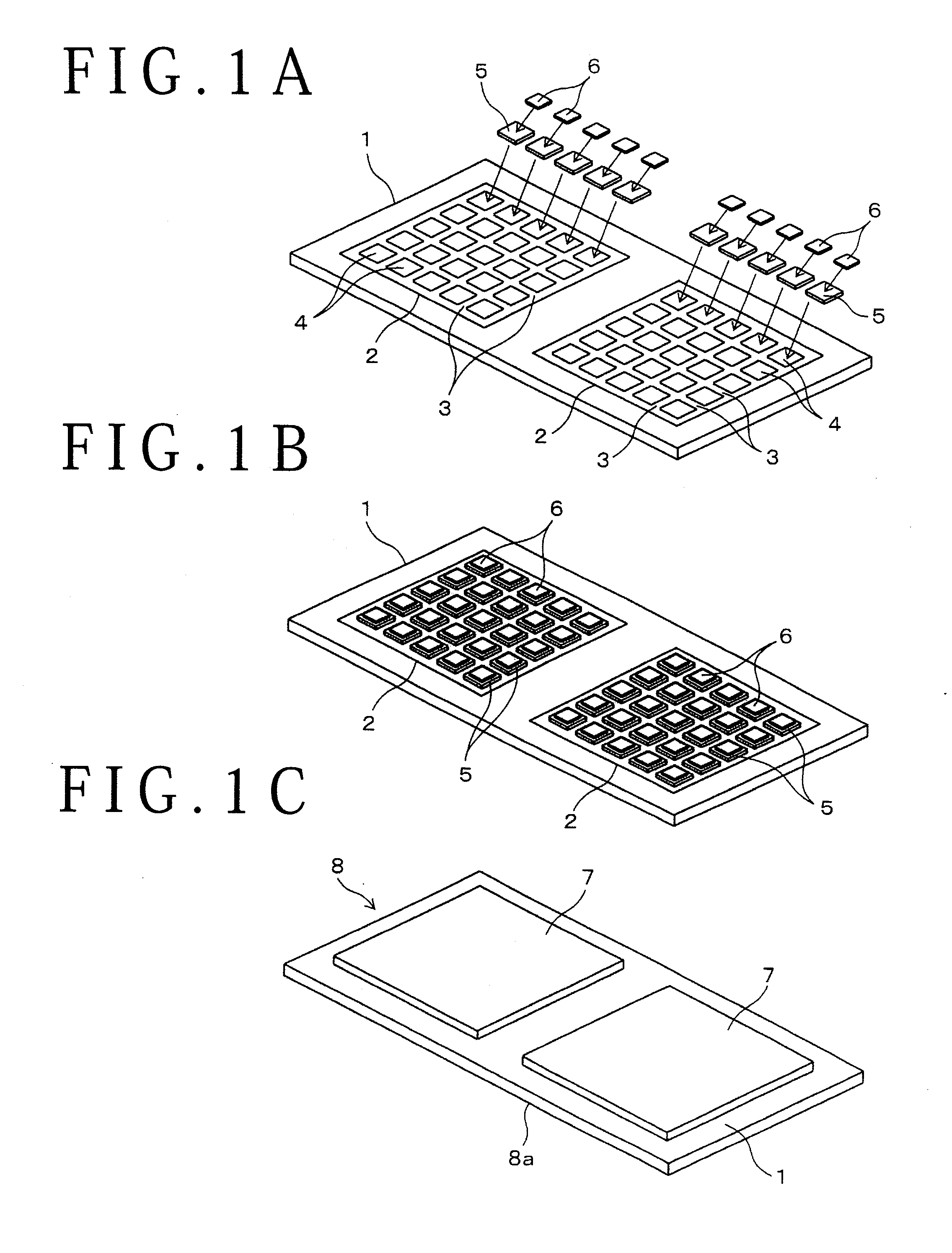
[0030]FIGS. 1A to 1C show a fabrication procedure for a package base according to the present invention, wherein reference numeral 1 denotes a rectangular substrate for semiconductor packages. As shown in FIG. 1A, the front surface (upper surface) of the substrate 1 is formed with a plurality of (two in this preferred embodiment) rectangular chip mounting areas 2. Each chip mounting area 2 is partitioned by a plurality of crossing cutting lines 3 to define a plurality of chip stacking portions 4 arranged like a matrix. A package base 8 shown in FIG. 1C is fabricated in the following manner. First, a first semiconductor chip 5 and a second semiconductor chip 6 are stacked and bonded on each chip stacking portion 4 of the substrate 1 as shown in FIGS. 1A and 1B, and electrical connection is made between the chips 5 and 6 and between the chips 5 and 6 and the subst...


PUM

PropertyMeasurementUnit
pressureaaaaaaaaaa
sizeaaaaaaaaaa
thicknessaaaaaaaaaa

Abstract

A package base is held on a holding table, and an XYZ moving mechanism is next moved to adjust a jet position to a cutting start point of a primary subject line to be first cut. Thereafter, a cutting water supplying unit is operated to direct a water jet onto the package base at this cutting start point. Thereafter, the XYZ moving mechanism is operated to move the package base, thereby cutting the package base along the primary subject line until a cutting stop point. Similarly, this cutting operation is repeated for the other primary subject line to thereby obtain a plurality of primary cut areas having the same shape and size in the condition that each primary cut area is integrally supported at its opposite ends to the package base, thus finishing a primary cutting step. Thereafter, a dicing tape is attached to one side surface of the package base. Thereafter, the package base is cut along a plurality of secondary subject lines as in the primary cutting step, thus finishing a secondary cutting step.

Description

BACKGROUND OF THE INVENTION[0001]1. Field of the Invention[0002]The present invention relates to a method of cutting a workpiece such as a substrate, and more particularly to a method of cutting a workpiece by jetting a high-pressure cutting water to the workpiece.[0003]2. Description of the Related Art[0004]A plurality of individual devices such as semiconductor chips are fabricated by partitioning the surface of a wafer into a plurality of rectangular areas arranged like a matrix, forming an electronic circuit such as IC (Integral Circuit) or LSI (Large Scale Integration) in each rectangular area, and cutting the wafer along a plurality of cutting lines defining the rectangular areas therein. The wafer is cut by using a dicing device having a cutting blade or a laser cutting device using laser light. In some case, each device is packaged by a packaging technique called CSP (Chip Size Package) intended to downsizing.[0005]In a QFN (Quad Flat Non-leaded) package as an example of the...

Claims


Application Information

Patent Timeline
Patent Type & Authority Applications(United States)
IPC IPC(8): B26D7/00
CPCB26D7/01B26F3/004H01L21/67092Y10T83/0443
Inventor KANAI, SHIGEKAZU
Owner DISCO CORP
Learn More