[0017]Even a further object of the present invention is to provide a snap lock separatory panel and retainer system that is easy to use and which takes little time to assemble and to remove.
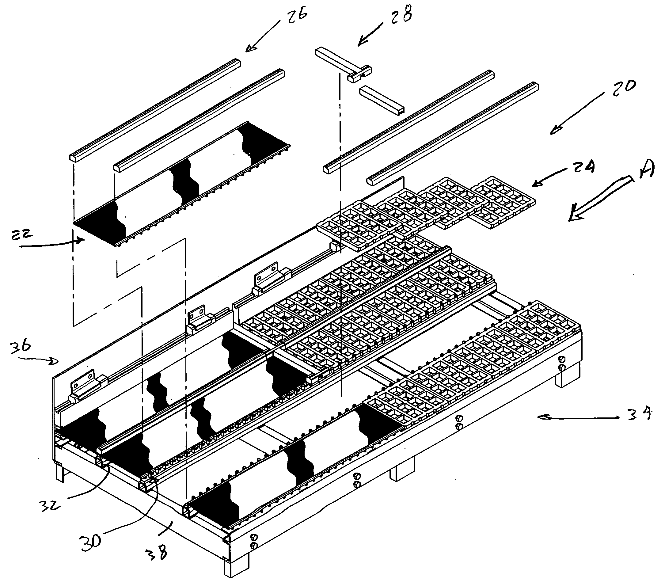
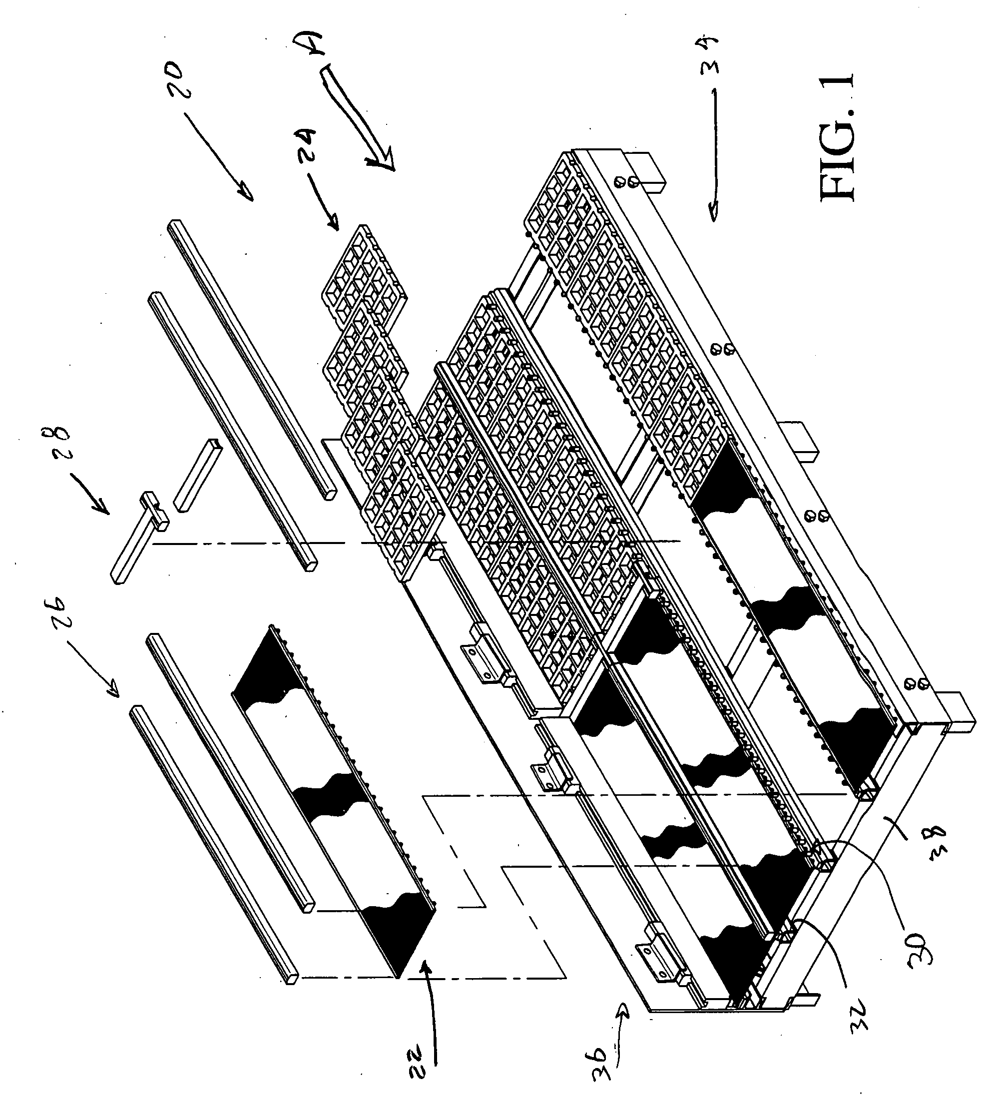
[0018]As will be described in detail in the description of the preferred embodiment, which is set forth subsequently, the snap lock separatory panel and retainer system in accordance with the present invention is an improvement over the assignee's prior system, as described in U.S. Pat. No. 6,964,341 to Bacho et al. In the present invention, a center retainer is securable to the stringer screen rails of a generally conventional vibrating separating machine. As was the case in the prior Bacho et al. patent, the center retainer includes a center retainer spine that may be encased in, or which may be supported by, a resilient material, such as
polyurethane, and which includes a plurality of spaced, upwardly projecting pins. Each such pin features an enlarged head that projects above the center retainer spine and its resilient sheathing. Each of these pins is sized and spaced to cooperate with a locking strip having a plurality of
undercut receptacles extending into the locking strip from a bottom surface thereof. The enlarged heads of the pins are securable in the individual receptacles in the locking strip thus providing a snap fit between the center retainer and the locking strip. Such a snap fit is both secure and easily taken apart.
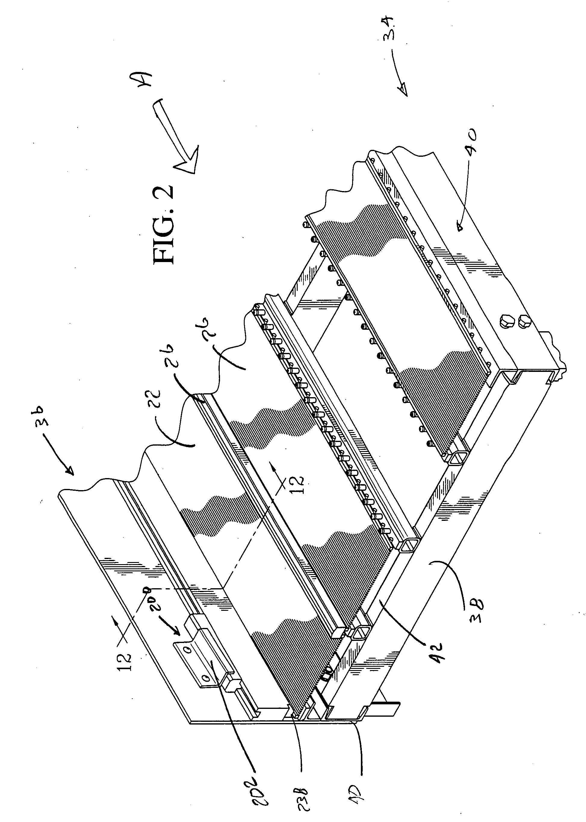
[0021]In the snap lock separatory panel and retainer system in accordance with the present invention, there is a unique cooperation between the structure of the center retainer, its cooperating locking strip, and the separatory panel which is being retained. This unique relationship provides for a tight, positive, reliable fitment of the separatory panels in the vibrating separatory machine. It also insures that the screen panels will have a degree of structural stiffness that is not present in typical screen panels. The utilization of the screen locking bars at both of the longitudinal sides of each screen panel provides a resistance to flexure that allows the screen panels to stay in place on the center retainer. The
sizing of the screen locking bars insures that they will be positively engaged by both an upper surface of the center retainer, and a lower surface of the locking strip. This positive clamping of the screen locking bars insures that the screen panels will not move or become dislodged. Similarly, the structure and
dimensioning of the locking flanges of the urethane panels will insure that these panels are positively engaged and held in place.
[0022]The snap lock separatory panel and retainer system in accordance with the present invention is much more easily used than the prior systems that it is intended to replace. The upwardly projecting pins are not susceptible to damage or breakage. They do not become bent or worn during use. They are engaged by the undercut receptacles in the locking strips, and once those locking strips have been snapped into place, the pins are out of
sight and are protected. The locking strips are simple, one piece construction that are not structurally complex and which can be easily replaced as they become worn. The center retainers are ensheathed in a resilient material, such as
polyurethane, or are made from a formable material, such as nylon or other materials such as UHMW plastic, and are protected from the
abrasive slurry that is being separated, by the locking strips and by the locking profiles on outboard ends of the separatory panels. Suitable cross dams can be utilized, in conjunction with the locking bars, to control the flow of the
slurry which is being separated by the vibrating separatory machinery. Selected ones of these cross dams include ends that have the undercut receptacles, similar in their arrangement to that of the locking strips. The spacing between successive ones of these transverse dams is typically the same as in prior separatory devices. The dams thus typically overlie junctions between adjacent ones of the separatory panels, in the direction of the flow of the slurry that is to be separated.
[0023]Instead of supporting separatory panels comprised of a plurality of screen panels, having profile screen wires, the vibrating separatory machine can utilize separatory panels comprised of a plurality of urethane panels that also act to separate materials, and which urethane panels can also be secured by the center retainers and locking strips. The longitudinal sides of these urethane panels can be
cut to receive the upstanding pins of the center retainer. The height of the urethane panel sides is substantially the same as the height of the screen panels and screen panel locking bars. Each urethane panel longitudinal side includes a
flange that forms that panel's locking profile. The locking strips thus again will snap fit onto the enlarged heads of the pins. This again will insure that the urethane screen panels are positively secured to the screen stringer rails of the vibrating separatory machinery and will not become loose or dislodged.
[0024]Removal of old or worn screen panels or urethane panels from the body of the separatory machinery is easily and quickly accomplished. Each locking strip and cross dam is removable simply by inserting a thin tool blade between one end of a locking strip and an upper surface of one of the panel locking profiles. Upward prying motion exerted on the tool will separate the first several pins of the center retainer from their respective undercut receptacles on the locking strip. Once this initial separation has been accomplished, the locking strip can be easily pulled up and removed. As soon as the locking strips and cross dams have been pried off, the screen panels or the urethane panels can be elevated vertically and can then be easily removed from the vibrating separatory machine. The center retainer bar remains in place, attached to the screen stringer rails. Since the upwardly projecting pins of the center retainer bar are never exposed to the
abrasive slurry, because they are covered by the locking strips when the machinery is in use, they typically do not need to be removed or replaced. The holes in the screen stringer rails will not be exposed to the
abrasive slurry and will not enlarge to any substantial extent. Any such hole enlargement will be compensated for by the adjustable radial expansion of the lower ends of the selected ones of the retainer pins which are receivable in the holes in the screen stringer rails.

