Antenna duplexer

a duplexer and duplexer technology, applied in the field of duplexers, can solve the problems of reducing dimensions and difficulty in securing a sufficient space, and achieve the effect of small size and lower heigh

Active Publication Date: 2008-11-20
TAIYO YUDEN KK
View PDF4 Cites 48 Cited by
  • Summary
  • Abstract
  • Description
  • Claims
  • Application Information

AI Technical Summary

Benefits of technology

[0031]The present invention has been accomplished in view of the foregoing situation, with an object to provide an antenna duplexer that can be built in a smaller size and lower height than ever without compromise in attenuation and isolation characteristic, by achieving an innovative ground pattern layout of the package.

Problems solved by technology

However, attempting to reduce the dimensions including the height of the package imposes difficulty in securing a sufficient space for arranging the ground pattern.
The attenuation in the transmission band and isolation characteristic are quite susceptible to the layout of the ground pattern of the longitudinal mode coupled filter, and therefore special attention has to be paid to the layout of the ground pattern.

Method used


Image

  • Antenna duplexer
  • Antenna duplexer
  • Antenna duplexer

Examples


first embodiment

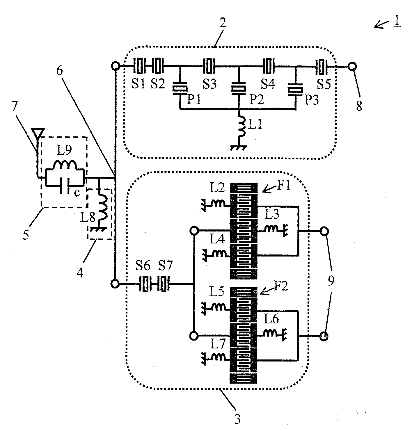
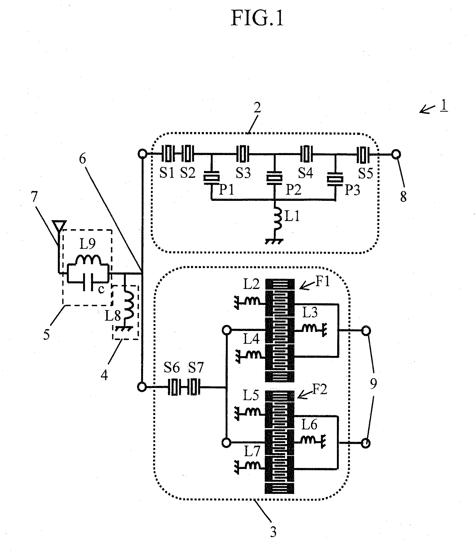
[0086]FIG. 1 is a circuit diagram of an antenna duplexer according to the present invention. The antenna duplexer 1 includes a transmit filter 2, a receive filter 3, a matching circuit 4, and a notch circuit 5.

[0087]The transmit filter 2 is a ladder-type filter including five serial resonators S1 to S5 and three parallel resonators P1 to P3, and a piezoelectric thin film resonator is employed as each of the resonators S1 to S5 and P1 to P3. The three parallel resonators P1 to P3 are commonized on the side of the ground, and then connected to an inductor L1. The inductor L1 is constituted of a conductor pattern including a via, in the package. In this embodiment, two serial resonators S1, S2 are connected in series on the side of the antenna terminal 7 in the transmit filter 2, in order to improve the power-withstanding capability and linearity of harmonic distortion and so on of the antenna duplexer 1.

[0088]The receive filter 3 includes two double mode type surface acoustic wave fil...

second embodiment

[0149]FIG. 15 is a circuit diagram of an antenna duplexer according to the present invention.

[0150]The antenna duplexer 1′ according to the second embodiment is different from the antenna duplexer 1 shown in FIG. 1 in the structure of the receive filter 3′. More specifically, the receive terminal 9′ of the receive filter 3′ is unbalanced. Accordingly, to obtain an unbalanced output from the receive terminal, the IDTs of the double mode type surface acoustic wave filters F1′ and F2′ are disposed in the same layout.

third embodiment

[0151]FIG. 16 is a circuit diagram of an antenna duplexer according to the present invention.

[0152]A difference of the antenna duplexer 1″ according to the third embodiment from the antenna duplexer 1 shown in FIG. 1 also lies in the structure of the receive filter 3′. More specifically, a ladder-type filter constituting the transmit filter 2 is also employed as the receive filter 3′. In the antenna duplexer 1″ according to the third embodiment also, the receive terminal 9″ of the receive filter 3″ is unbalanced.

[0153]The circuit configuration according to the second and the third embodiment provides an antenna duplexer in which the antenna terminal, the transmit terminal, and the receive terminal are all unbalanced. The details of the circuit configuration are the same as those of the first embodiment, and hence will not be repeated.

[0154]Thus, the present invention provides an antenna duplexer of a significantly smaller size and lower height than ever, yet capable of achieving hig...


PUM


Abstract

An antenna duplexer is provided, which can be built with a smaller size and lower height than ever without compromising out-of-band attenuation characteristic and isolation characteristic between a transmit terminal and a receive terminal. The antenna duplexer includes a transmit filter provided between an antenna terminal and the transmit terminal, and a receive filter provided between the antenna terminal and the receive terminal. The filters are enclosed by a package, in which a ground pattern for the receive filter is separated from other ground patterns.

Description

BACKGROUND OF THE INVENTION[0001]1. Field of the Invention[0002]The present invention relates to an antenna duplexer that separates a transmit signal and a receive signal.[0003]2. Description of the Related Art[0004]The recent development of mobile communication system has realized rapid popularization of mobile phones, portable information terminals and the like. In the field of the mobile phone, multiband and multimode systems are rapidly spreading, and besides accessorial wireless interface functions such as wireless LAN, Bluetooth, or GPS are being added one after another. Such situation is provoking a strong demand for further reduction in dimensions and higher integration level of RF circuits in the mobile phone and hence, in turn, a greater demand is arising for reduction in dimensions, lower cost yet higher performance of an antenna duplexer, which is one of the major components of the RF circuit.[0005]The antenna duplexer is employed for separating a transmit signal and a r...

Claims


Application Information

Patent Timeline
Patent Type & Authority Applications(United States)
IPC IPC(8): H03H9/70
CPCH03H9/0576H03H9/725H03H9/25H03H9/54H03H9/64
Inventor NISHIHARA, TOKIHIROIWAKI, MASAFUMITANIGUCHI, SHINJIUEDA, MASANORIENDO, GOHATANO, KOICHI
Owner TAIYO YUDEN KK
Why Eureka
Try Eureka