
Backlight Device and Transmission Type Liquid Crystal Display Apparatus

a liquid crystal display and transmission technology, applied in the direction of optics, instruments, optical light guides, etc., can solve the problems of uneven dimensional accuracy, poor uniformity ratio, etc., and achieve the effect of preventing color unevenness and/or lateral stripe, and high luminan

Inactive Publication Date: 2008-11-20
SONY CORP
View PDF10 Cites 85 Cited by
  • Summary
  • Abstract
  • Description
  • Claims
  • Application Information

AI Technical Summary

Benefits of technology

[0013]An object of the present invention is to provide a backlight device and a transmission type liquid crystal apparatus which solve the problems of prior arts conventionally proposed or conceived as described above, and adapted so that a large number of light emitting diodes are provided to perform realization of high luminance of the transmission type liquid crystal panel and to prevent occurrence of color unevenness and / or lateral stripe.
[0015]In the backlight device to which the present invention is applied, rays of display light which have been emitted from the respective light emitting diodes of the light source blocks are delivered to the display panel through the light diffusion plate. Thus, display of high luminance is performed at the display panel. Namely, at the light diffusion plate, light adjustment patterns formed in the state facing respective light emitting diodes serve to reflect display light to reduce occurrence of partial high luminance region. Thus, the display light is delivered from the entire surface of the light diffusion plate to the display panel in uniformed state.
[0016]In the backlight device to which the present invention is applied, even if slight positional shift takes place between light emitting diodes and light adjustment patterns which are opposite to each other in assembled state, transmission / reflection function by light adjustment pattern larger than the light emitting diode is held to deliver display light from the entire surface of the light diffusion plate to the display panel in uniformed state. Further, respective light adjustment patterns formed so as to take longitudinal elongated shape serve to suppress light transmission factor of display light in respective inter-column direction of the light source blocks with respect to rays of display light which have been emitted from the respective light emitting diodes. Moreover, the transmission type display panel realizes display of high accuracy in which occurrence of color unevenness, ramp image and / or lateral stripe has been prevented.
[0019]In the backlight device and the transmission type liquid crystal display apparatus using such backlight unit to which the present invention has been applied, a large number of light emitting diodes are caused to be light source to realize display of high luminance so that the opposite state with respect to respective light emitting diodes facing the respective light adjustment patterns are held also with respect to dimensional change of respective constituent members, and / or unevenness of dimensional accuracy, and / or assembling accuracy of respective constituent members, and / or print accuracy of light adjustment pattern resulting from the influence of heat produced from the respective light emitting diodes to reduce occurrence of partial high luminance regions at the light diffusion plate so that realization of reduction of color unevenness occurrence can be performed along with realization of high luminance of the display panel.
[0020]In addition, in the present invention, occurrence of partial high luminance region at the light diffusion plate, which is produced between columns of respective light source blocks, is also reduced so that it is prevented that lateral stripe takes place at the display panel.

Problems solved by technology

However, it is necessary to solve the problems that light emitting luminance that the cold cathode fluorescent lamp has is low, lifetime is short, and / or low luminance region exists at the cathode side so that uniformity ratio, etc. is bad, etc.
Particularly, in the case where the area litconfiguration backlight unit is applied to such a large sized television image receiver having size above 40 inches, the problems of realization of high luminance and / or realization of high uniformity ratio become more conspicuous.
Moreover, in the LED backlight unit, positional shift between LEDs and the light adjustment patterns which are opposite to each other may take place by unevenness of dimensional accuracy and / or assembling accuracy of the liquid crystal panel, the light source unit or the light diffusion plate, and print accuracy of the light adjustment pattern, etc.
In the LED backlight unit, it was difficult to extremely perform positioning of the LEDs and the light adjustment patterns with high accuracy because the above-described various factors are concerned.
As a result, it was difficult to reduce the cost.
Thus, there become conspicuous the problems that color unevenness and / or ramp image may take place in the liquid crystal panel, etc.
Thus, color unevenness of lateral stripe may disadvantageously take place at the liquid crystal panel.
In the LED backlight unit, in the case where, e.g., a larger number of LEDs are used so that compliance of realization of high luminance is performed, not only cost is increased and / or power consumption becomes larger, but also it becomes difficult to extremely comply with larger heat.

Method used


Image

  • Backlight Device and Transmission Type Liquid Crystal Display Apparatus
  • Backlight Device and Transmission Type Liquid Crystal Display Apparatus
  • Backlight Device and Transmission Type Liquid Crystal Display Apparatus

Examples


Embodiment Construction

[0030]Embodiments of a transmission type liquid crystal color liquid crystal display apparatus (hereinafter simply referred to as liquid crystal display apparatus) to which the present invention is applied will be explained with reference to the attached drawings.

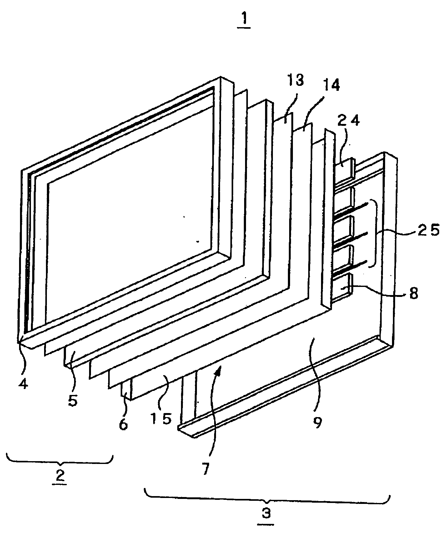
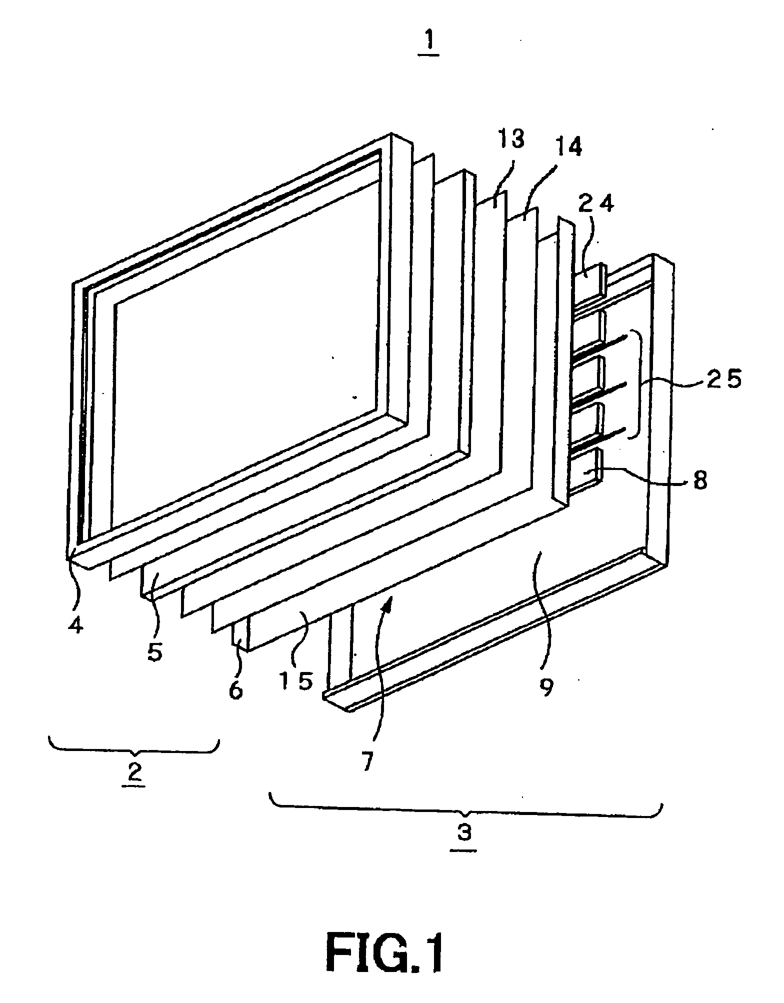
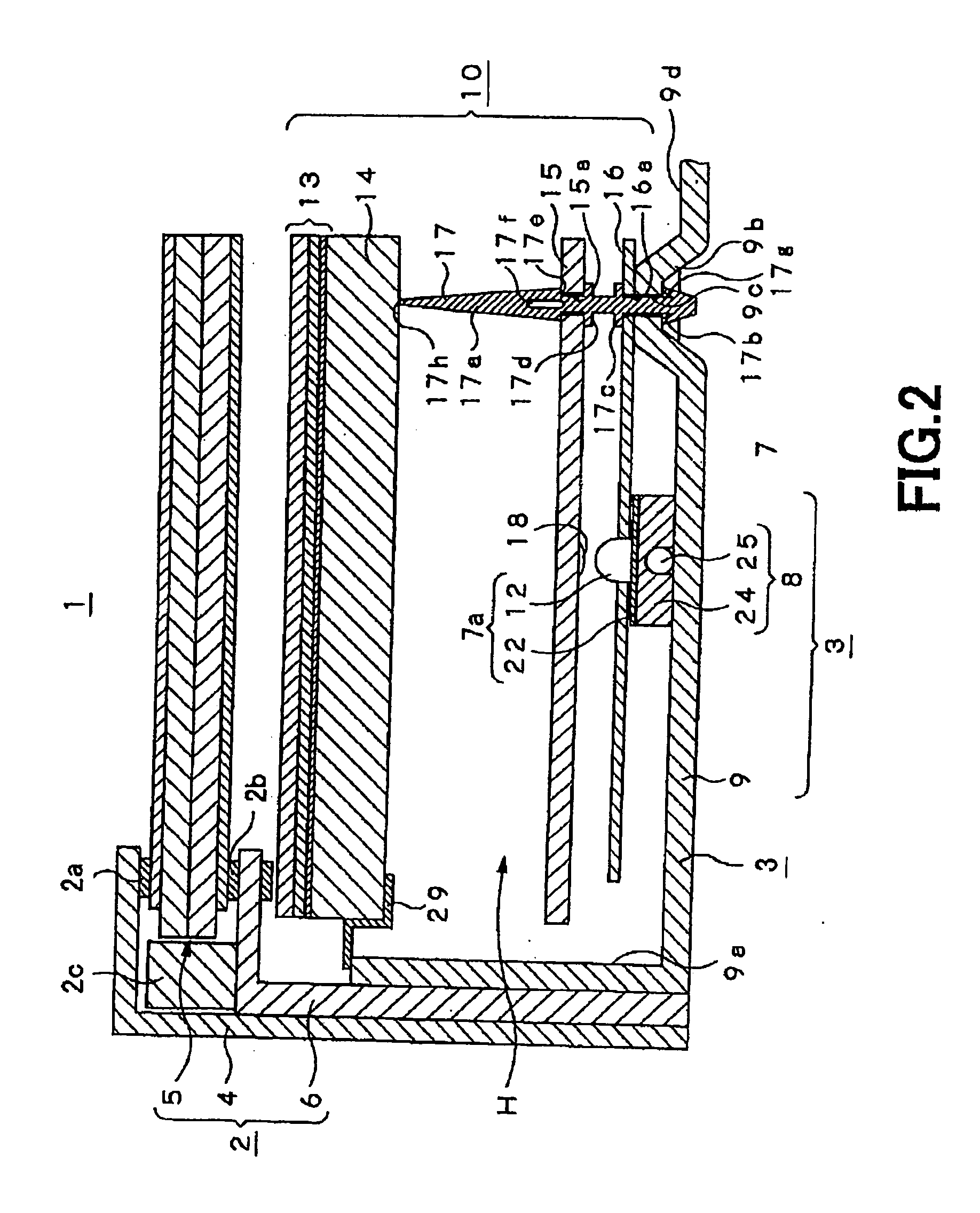
[0031]The liquid crystal display apparatus 1 according to the present invention is used for display panel of television image receiver having large-sized display screen above, e.g., 40 inches, and / or display monitor, etc. As shown in FIGS. 1 and 2, the liquid crystal display apparatus 1 comprises a liquid crystal panel unit 2, and a backlight unit 3 combined with the rear face side of the liquid crystal panel unit 2 and serving to deliver display light. The liquid crystal panel unit 2 is composed of a frame-shaped front face frame member 4, a liquid crystal panel 5, and a frame-shaped rear face frame member 6 for holding the outer peripheral edge portion of the liquid crystal panel 5 through spacers 2a, 2b and guide member ...


PUM

PropertyMeasurementUnit
sizeaaaaaaaaaa
length W2aaaaaaaaaa
length W2aaaaaaaaaa

Abstract

A transmission liquid crystal display device using a backlight device for supplying display light emitted from a large number of light emission diodes to a transmission display panel. The transmission liquid crystal display device has an optical sheet block (10) between a liquid crystal panel (5) and a light source unit (7) having a large number of LEDs (12) and has a light diffusion plate (15), which has light transmission properties and is made of resin, for controlling the incidence of display light emitted from each of the LEDs (12). On the light diffusion plate (15) are formed vertically long light modulation patterns (18) by using light reflective ink. Each pattern (18) faces each LED (12) and has a size equal to the size of each LED (12) including its external shape. The light modulation patterns (18) uniformize the light emitted from the LEDs (12) and realize an image display of high brightness where color irregularity and horizontal stripes are suppressed.

Description

TECHNICAL FIELD[0001]The present invention relates to a backlight device adapted for delivering rays of display light which have been emitted from a large number of light emitting diodes to a transmission type display panel, e.g., transmission type Liquid Crystal Display (LCD), etc., and a transmission type liquid crystal display apparatus using such a backlight device.[0002]This Application claims priority of Japanese Patent Application No. 2004-238786, filed on Aug. 18, 2004, the entirety of which is incorporated by reference herein.BACKGROUND ART[0003]Since Liquid Crystal Display apparatuses can realize large-sized display screen, light weight, thin structure and / or low power consumption, etc. as compared to Cathode-Ray Tube (CRT), they are used in Television Image Receiver and / or display apparatus for various display purposes along with, e.g., self-light emitting type Plasma Display Panel (PDP), etc. In the liquid crystal display apparatus, liquid crystals are included between t...

Claims


Application Information

Patent Timeline
Patent Type & Authority Applications(United States)
IPC IPC(8): G02F1/1335G02B5/02
CPCG02B6/0073G02F1/133603G02F1/133606G02F1/133611
Inventor MAHAMA, KAZUTOSHIHATANAKA, MASATO
Owner SONY CORP
Learn More