LCD displays with light redirection

a liquid crystal display and backlight technology, applied in lighting and heating equipment, manufacturing tools, instruments, etc., can solve the problems of prone to warping in manufacture, less and less desirable conventional flat panel backlight solutions using side-mounted ccfls, and insufficient image quality of lcd displays

Inactive Publication Date: 2008-11-20
SKC HAAS DISPLAY FILMS CO LTD
View PDF16 Cites 86 Cited by
  • Summary
  • Abstract
  • Description
  • Claims
  • Application Information

AI Technical Summary

Benefits of technology

[0018]It is a further advantage of the present invention that it may be used with light guide plate or other planar type panel, As well as elongated illuminators.
[0019]These and other objects, features, and advantages of the present invention will become apparent to those skilled in the art upon a reading of the following detailed description when taken in conjunction with the drawings wherein there is shown and described an illustrative embodiment of the invention.

Problems solved by technology

While liquid crystal displays (LCDs) offer a compact, lightweight alternative to cathode ray tube (CRT) monitors, there are many applications for which the image quality of LCD displays are not yet satisfactory, particularly as the relative size of these devices increases.
Conventional flat panel backlight solutions using side-mounted CCFLs are less and less desirable as display size increases and, particularly as display area grows, can be susceptible to warping in manufacture or due to heat.
Light-guiding backlight techniques that are conventionally employed for smaller devices are increasingly hampered by low brightness or luminance levels and by problems related to poor uniformity as the display size increases, such as would be needed for digital TV, for example.
Existing backlight apparatus for LCD displays and other display and illumination applications, often using banks of CCFLs lined up in parallel, can be relatively inefficient.
The CCFL light source itself presents an environmental problem for disposal, since these devices contain some amount of mercury.
As is well known, the spectral characteristics of CCFLs are relatively poor when compared to other types of light sources.
However, except for specialized uses such as for some types of instrument panels and for very high-end monitors and TV panels, array arrangements do not appear promising, due to problems of poor color and brightness uniformity, high parts count, high heat, and dimensional requirements.
However, although there have been a number of solutions proposed, there are significant drawbacks inherent to each type of solution, particularly when faced with the problem of backlighting for a display panel of standard laptop dimensions or larger.
The 2-D matrix proposed in the '921 Deloy et al. disclosure would be difficult to implement inexpensively, of relatively high cost, bulky, and prone to uniformity problems.
The molded panel arrangement described in the '224 DuNah et al. disclosure may work well enough for general illumination, but would be prone to uniformity problems for full-color display applications.
This type of solution is increasingly expensive to manufacture in larger sizes and is subject to warping due to heat and mechanical stress.
More importantly, such a solution does not provide good color mixing and would not be well suited to applications using solid-state light sources.
Point source-to-panel configurations such as those described in the '3246 Parker application are impractical and exhibit uniformity problems for color and brightness for larger-sized displays.
Light-guide-to-back-panel arrangements such as those described in the '661 Tai et al. disclosure are inefficient, are subject to poor uniformity, and are suitable only for relatively small displays.
The use of treated optical fibers has advantages for small-scale handheld displays but would be impractical and inefficient for desktop or larger display designs.
In addition to these drawbacks, conventional solutions generally fail to address important challenges for high-quality color imaging, required for widespread commercialization and acceptance of LC displays.
Although this may be acceptable for laptop and computer monitor applications, it falls short of what is needed for full-color TV displays.
As is well known to those skilled in the imaging display art, achieving a good level of color uniformity when using solid-state light sources, such as Red (R), Green (G), and Blue (B) LEDs, is particularly challenging.
Conventional backlighting solutions that employ larger-area light guides, such as those described above, would provide correspondingly inferior color mixing.
Other challenges related to backlighting for larger scale displays include the need for low-cost assembly, light efficiency, uniformity, and compact size.
As noted earlier, conventional LED backlighting solutions fall short of what is needed to meet these additional requirements.
For larger displays being able to redirect or extract light in a uniform manner is difficult.

Method used


Image

  • LCD displays with light redirection
  • LCD displays with light redirection
  • LCD displays with light redirection

Examples


embodiments

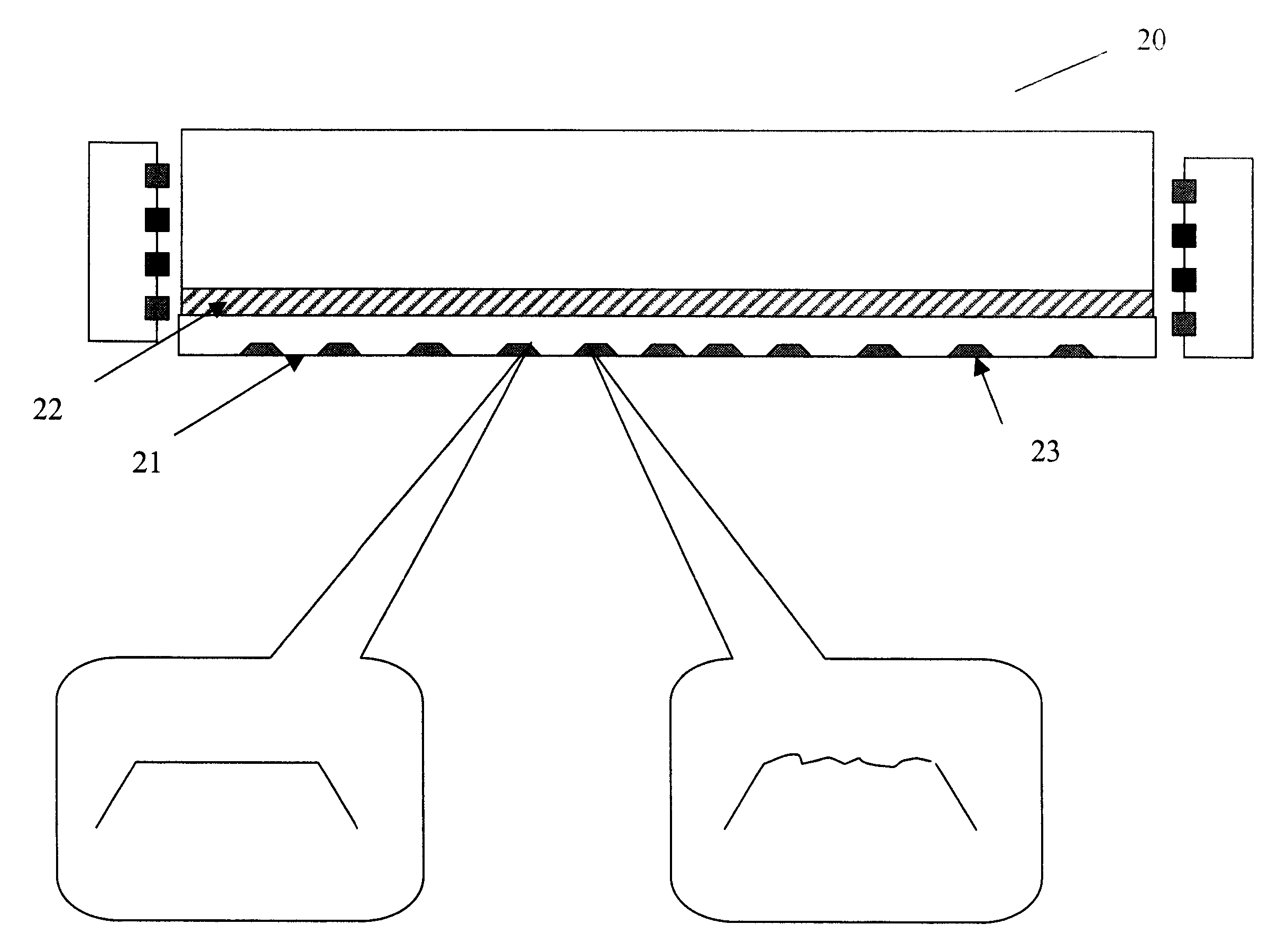
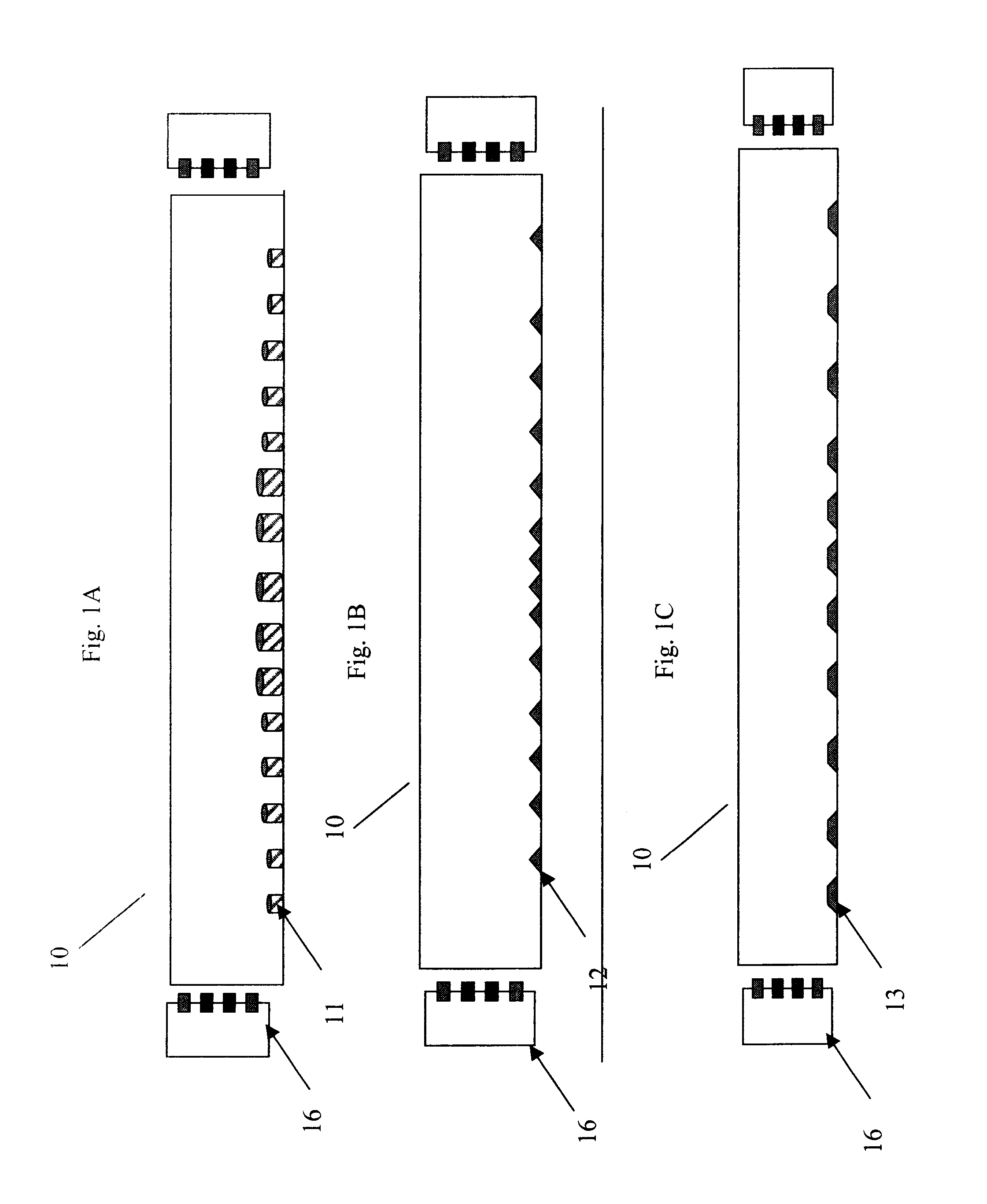
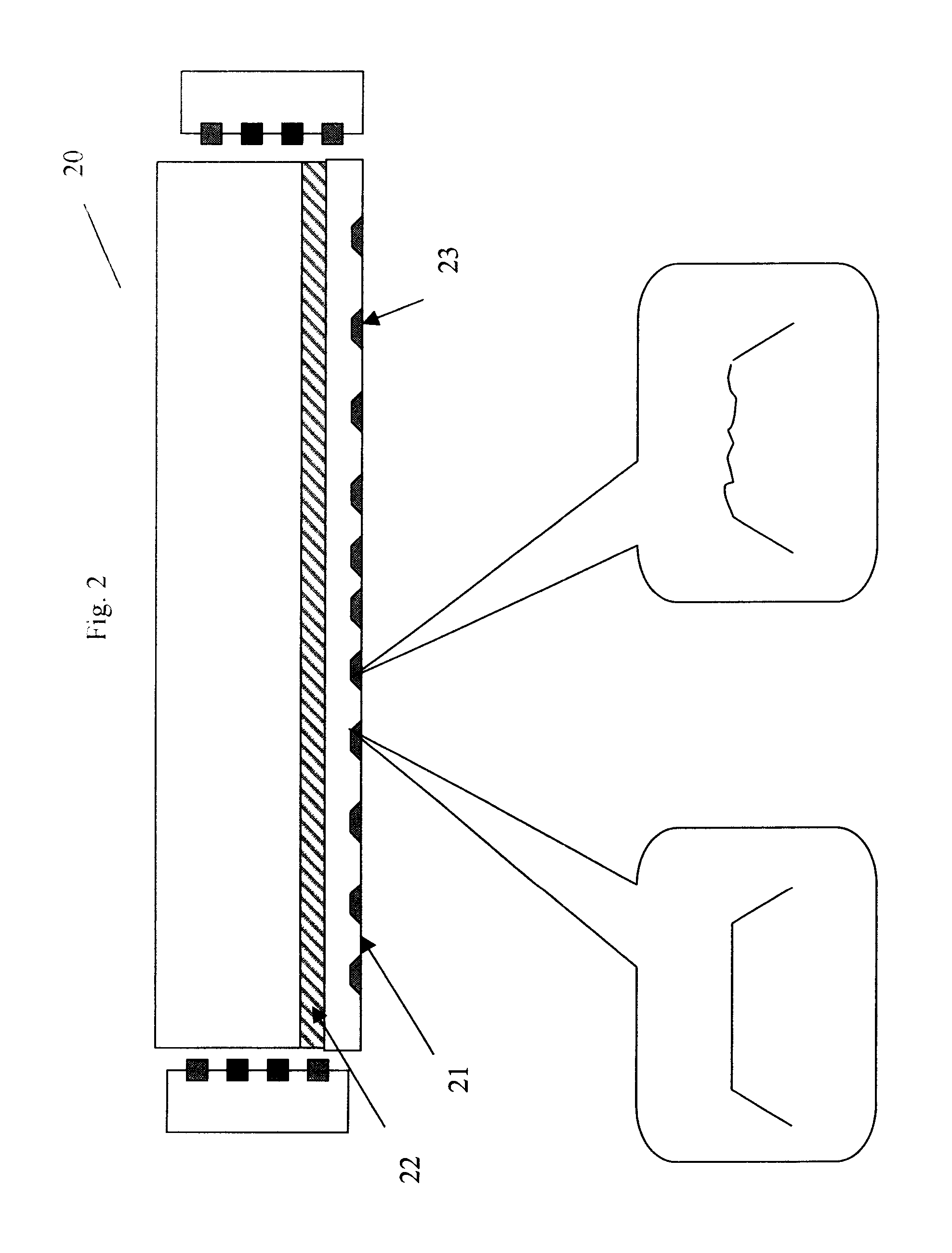
[0058]FIGS. 1A, 1B and 1C are side view cross sections of solid lightguide 10 with a series of holes or indents 11, 12 and 13 that are formed in the non-view side. The lightguide may be lit from one or both ends by light source 16. If lit from one end only, there may be a reflector on the end opposite the light source. The holes or indents may be any shape or size or may vary in shape and or size as a function of distance from the light source. In some embodiments the holes have the same relative size in the width and length dimensions. The features in general may be in the 1-300 micron size range in their depth although larger or slightly smaller may be desirable. The features are useful in scattering light and redirecting it towards the view side of the lightbar. The lightbar may be flat, tapered, round or other shape or compound shape. There may be a light mixing section to provide improved light mixing uniformity. The spacing, density, size and shape may be varied to provide uni...

examples

Sample 1

[0077]One embodiment uses an acrylic elongated illuminator with a nominally ¼ in. square in cross section. The elongated illuminator is highly transparent and has an optical finish on all sides and ends. To form the elongated illuminator bar stock of PMMA (0.25″×0.25″×14 inches was optically polished on a lathe and then hand polished with a slurry of fine grit to obtain a surface Ra of less than 25 nm. on the sides and on the light input end. The backside or non-view side of the bar was drilled with a pattern of holes to provide the desired light redirection. The holes were drilled to an approximate depth of 100 microns. The initial section from the light input section was not drilled. There was a section that was approximately 10-15 mm that had no holes. This section served has a color mixing section.

[0078]An LED array is used as light source. Multi-die RGB LEDs are mounted in close proximity to the light input end. These multi-die LEDS consist of 1 red, 1 blue and 2 green ...


PUM

PropertyMeasurementUnit
refractive indexaaaaaaaaaa
depthaaaaaaaaaa
depthaaaaaaaaaa

Abstract

A backlight apparatus for directing light toward a display panel and the resulting display device comprises a solid lightguide comprising opposite TIR surfaces, containing a desired pattern of light redirecting surface features located between the TIR surfaces and interrupting one of the TIR surfaces, the features having a refractive index differing from that of the solid material of the light guide. Such an apparatus provides a more even light distribution to the display.

Description

CROSS-REFERENCE TO RELATED APPLICATIONS[0001]This application is co-filed with an application under Attorney Docket No. 93845.FIELD OF THE INVENTION[0002]This invention relates to the art of backlight apparatus for a display and a liquid crystal display employing such apparatus. In particular, the present invention relates to a Liquid Crystal Display (LCD) backlight with solid-state light sources.BACKGROUND OF THE INVENTION[0003]While liquid crystal displays (LCDs) offer a compact, lightweight alternative to cathode ray tube (CRT) monitors, there are many applications for which the image quality of LCD displays are not yet satisfactory, particularly as the relative size of these devices increases. Larger LCD panels, such as those used in laptop computer or larger displays, are transmissive, and thus require a backlight. This type of light-providing surface, positioned behind the LCD panel, directs light outwards and towards the LCD.[0004]Conventional approaches for backlighting use ...

Claims


Application Information

Patent Timeline
Patent Type & Authority Applications(United States)
IPC IPC(8): F21V8/00C03B37/022G02B6/10
CPCG02B6/0028G02B6/0038G02B6/0068G02B6/0061G02B6/0043G02F1/1335G02F1/1337
Inventor AYLWARD, PETER T.BOURDELAIS, ROBERT P.HONG, QI
Owner SKC HAAS DISPLAY FILMS CO LTD
Why Eureka
Try Eureka