
Deadlock free network routing

a network routing and deadlock technology, applied in data switching networks, frequency-division multiplexes, instruments, etc., can solve the problems of increasing the probability of experiencing a fault, increasing the probability of faults, and more network components being broken, so as to improve the routing of networks

Inactive Publication Date: 2008-11-20
SIMULA INNOVATIONS
View PDF2 Cites 95 Cited by
  • Summary
  • Abstract
  • Description
  • Claims
  • Application Information

AI Technical Summary

Benefits of technology

[0009]It is an object of the present invention to overcome problems of the conventional routing schemes, and provide an improved routing of networks.

Problems solved by technology

As the number of components in the cluster increases, the probability of faults also increases.
Moreover, the components (processors, switches, and links) are often used close to their technology limits which also increases the probability of experiencing a fault—for large computer network it is more likely that one or more of the network components are broken at any time than that all of them are up and running.
However, in the presence of some switch or link failures, a regular network will become an irregular one.
The drawback of lossless networks is, however, that they are prone to deadlocks.
Another differential aspect is the computation cost of the routings.
As the number of possible routing paths among the same pair usually grows with system size, the computation time to achieve the best set of paths (one for each pair) may be too excessive for some critical scenarios (large topologies and real-time systems).
Additionally, as routing algorithms require different resources from the network, they may not be well suited for different technologies.
For instance, Infiniband specifications allows up to 15 virtual channels for routing purposes but real implementations may not implement virtual channels at all.
This means that routings schemes based on virtual layers may not be applied in these implementations.

Method used


Image

  • Deadlock free network routing
  • Deadlock free network routing
  • Deadlock free network routing

Examples


Embodiment Construction

[0056]In the following description, the following terminology is used, explained with reference to FIG. 2.

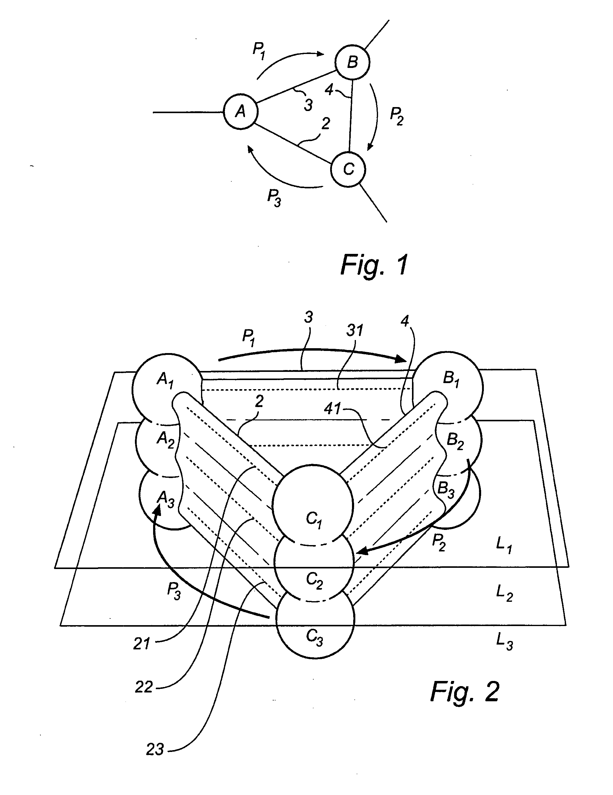
[0057]A network 1 comprises a plurality of nodes A, B, C, connected by physical links 2, 3, 4. A path P is a chain of links between a source node S and a destination node D.

[0058]Each physical link 2 may contain several channels 21, 22, 23, where each channel provides communication between two nodes A, B. The physical network can then be divided into (virtual) layers L1, L2, L3, where each virtual layer comprises a set of channels 21, 31, 41 providing the same connectivity as the physical links 2, 3, 4. A node A may further have several (virtual) addresses A1, A2, A3, so that there may be one set of addresses for each virtual layer L1, L2, L3.

[0059]A routing scheme defines a set of paths between any given pair of source node S and destination node D in a network, and a routing algorithm is used to determine a routing scheme. Based on a routing scheme, each node (switch) can be g...


PUM


Abstract

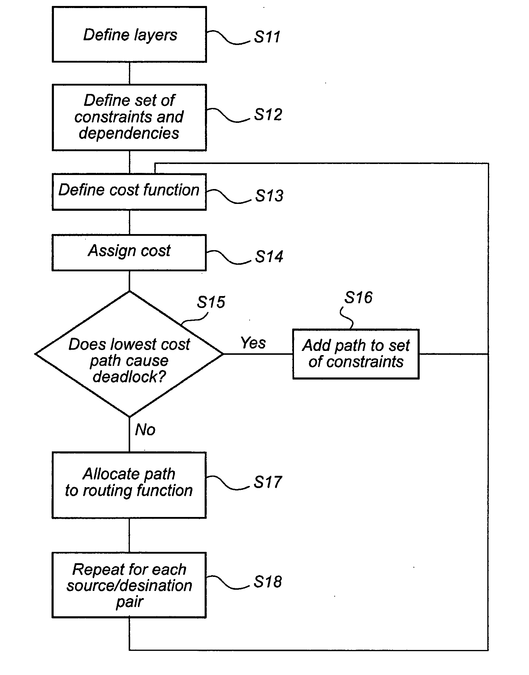
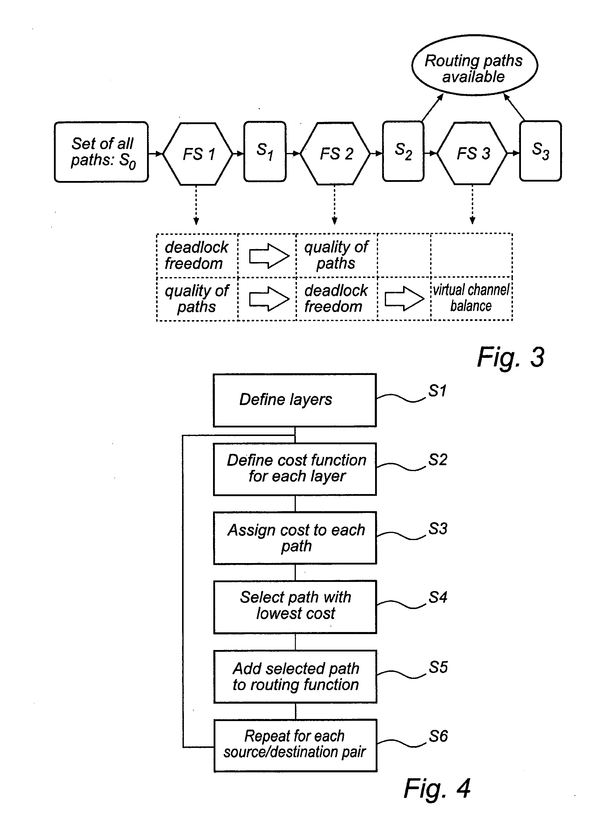
A method for establishing a routing scheme defining a path between any given pair of source node and destination node in a network including a plurality of nodes connected by links. The method comprises defining a plurality of virtual network layers, each virtual network layer comprising addresses for identifying each node, and channels for communicating between said nodes using said addresses, and defining a routing function for each layer, the routing scheme comprising all routing functions, each routing function comprising a set of source node / destination node pairs and a path connecting each pair. The routing function is defined by defining a cost function for each layer, said cost function being adapted to assign a high cost to any path creating a deadlock, using said cost function to assign a cost to each path in each layer connecting the source node / destination node pair, selecting the path with the lowest cost, and assigning the pair of source node / destination node and its selected path to the routing function of the layer that contains said selected path.According to this aspect of the invention, the number of virtual layers is defined initially, and the routing scheme is then generated using this number of layers. This provides complete control over the number of layers, so that it is possible to adjust the number of virtual layers to the capacity of the network.

Description

FIELD OF THE INVENTION[0001]The present invention relates generally to methods for establishing a routing scheme defining a path between any given pair of source node and destination node in a network including a plurality of nodes connected by links, and implementing such schemes in a network.BACKGROUND OF THE INVENTION[0002]During the last years, clusters of PCs (or Networks of Workstations, NOWs) are being considered as a cost-effective alternative to small and medium scale parallel computing systems. The performance of clusters is closely related to the advances in the interconnection network field. Currently, there are many proposals for NOW interconnects like Myrinet, Servernet II, Gigabit Ethernet, InfiniBand, and PCI Express ASI that allow to build high-performance clusters.[0003]As the number of components in the cluster increases, the probability of faults also increases. Moreover, the components (processors, switches, and links) are often used close to their technology li...

Claims


Application Information

Patent Timeline
IPC IPC(8): G08C15/00
CPCH04L12/462H04L45/00H04L45/12H04L45/64H04L45/66
Inventor LYSNE, OLAV
Owner SIMULA INNOVATIONS
Learn More