
Parametric audio system

a technology of audio system and parametric waveform, applied in the field of parametric waveform, can solve the problems of difficult to minimize the distortion of regenerated audio signal, 2-5 khz, narrow bandwidth of piezoelectric transducer used therewith, etc., and achieve the effect of minimizing ultrasound generation and maximizing the modulation depth of signal

Inactive Publication Date: 2008-11-20
POMPEI FRANK JOSEPH
View PDF31 Cites 40 Cited by
  • Summary
  • Abstract
  • Description
  • Claims
  • Application Information

AI Technical Summary

Benefits of technology

The system provides increased bandwidth and reduced distortion in airborne audio signals while being less costly to manufacture, with the ability to electronically steer audio beams, minimizing the need for mechanical steering devices.

Problems solved by technology

One drawback of the above-described conventional parametric audio system is that the piezoelectric transducers used therewith typically have a narrow bandwidth, e.g., 2-5 kHz.
As a result, it is difficult to minimize distortion in the regenerated audio signals.
However, because the typical piezoelectric transducer has a diameter of only about 0.25 inches, it is often necessary to include hundreds or thousands of such piezoelectric transducers in the acoustic transducer array to achieve an optimal acoustic transducer surface area, thereby significantly increasing the cost of manufacture.
Another drawback of the conventional parametric audio system is that the ultrasonic signal is typically directed along the selected projection path by a mechanical steering device.
However, such mechanical steering devices are frequently expensive, bulky, inconvenient, and limited.

Method used


Image

  • Parametric audio system
  • Parametric audio system
  • Parametric audio system

Examples


Embodiment Construction

[0021]The entire disclosure of U.S. patent application Ser. No. 09 / 758,606 filed Jan. 11, 2001 entitled PARAMETRIC AUDIO SYSTEM is hereby incorporated by reference herein.

[0022]Methods and apparatus are disclosed for directing ultrasonic beams modulated with audio signals through the air for subsequent regeneration of the audio signals along selected paths of projection. The presently disclosed invention directs such modulated ultrasonic beams through the air by way of a parametric audio system configured to provide increased bandwidth and reduced distortion in an implementation that is less costly to manufacture.

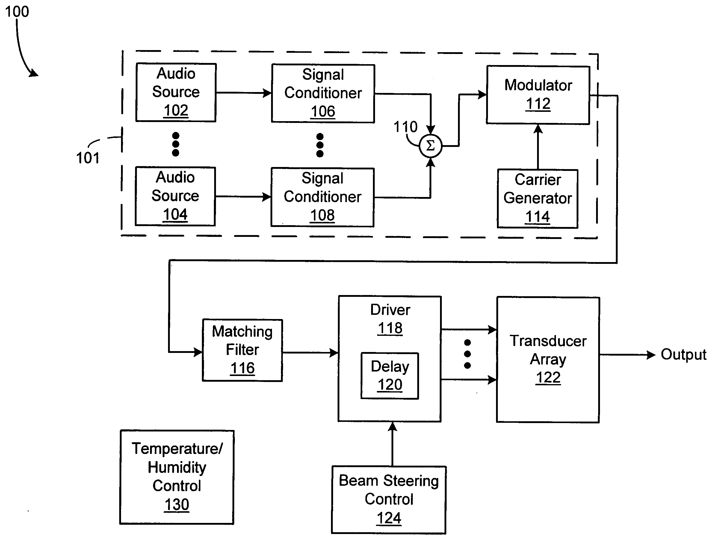
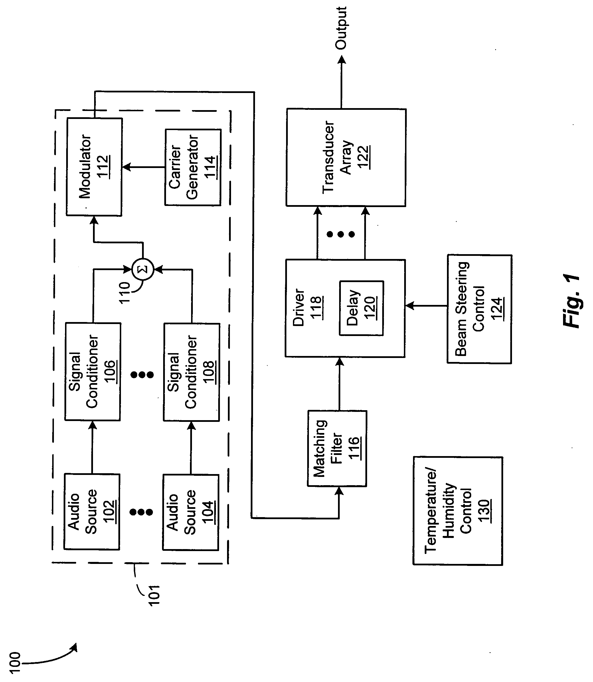
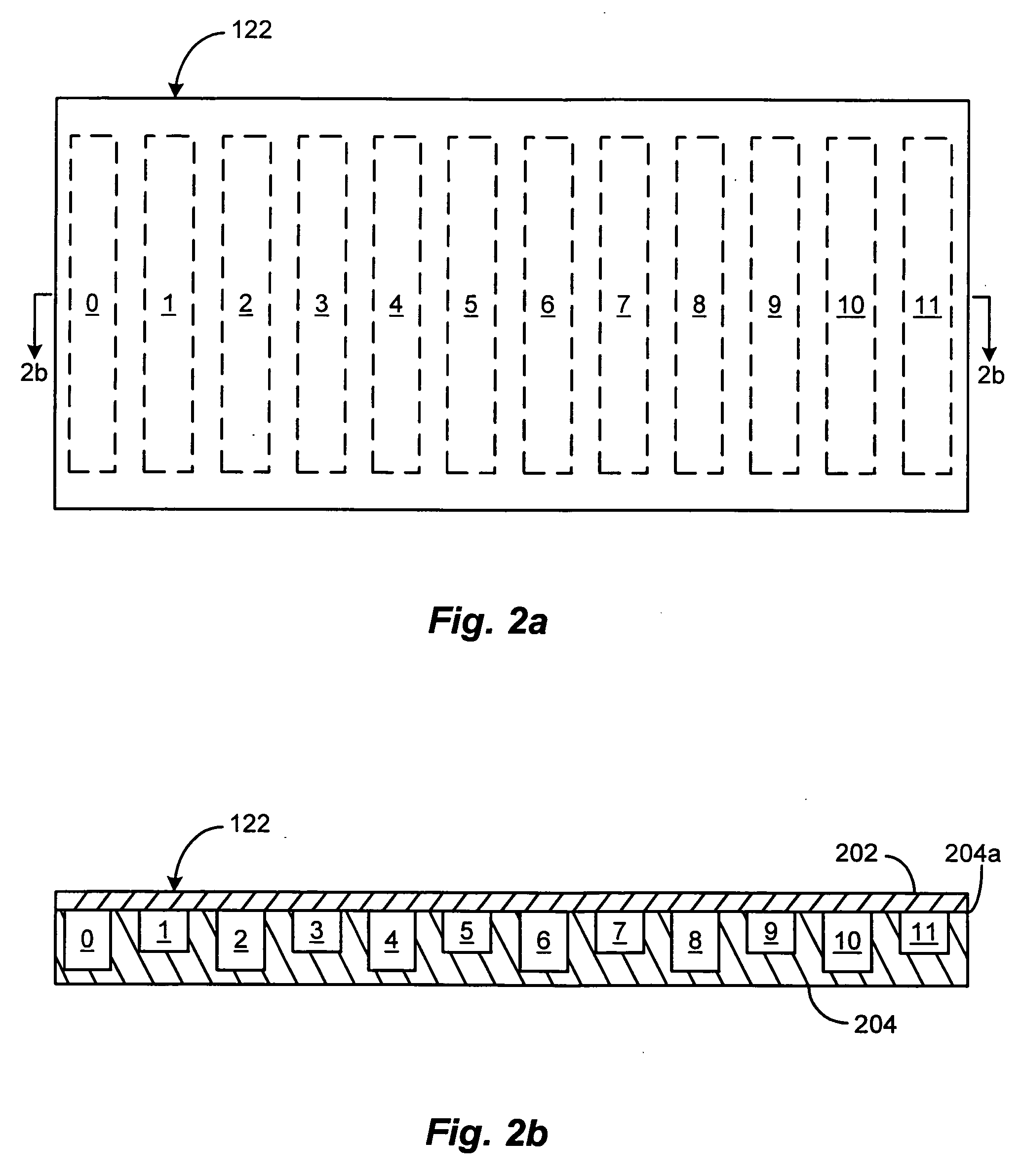
[0023]FIG. 1 depicts a block diagram of an illustrative embodiment of a parametric audio system 100 according to the present invention. In the illustrated embodiment, the parametric audio system 100 includes an acoustic transducer array 122 comprising a plurality of acoustic transducers arranged in a one, two, or three-dimensional configuration. The acoustic transducers of ...


PUM


Abstract

A parametric audio system having increased bandwidth for generating airborne audio signals with reduced distortion. The parametric audio system includes a modulator for modulating an ultrasonic carrier signal with a processed audio signal, a driver amplifier for amplifying the modulated carrier signal, and an array of acoustic transducers for projecting the modulated and amplified carrier signal through the air along a selected projection path to regenerate the audio signal. The acoustic transducer array includes a backplate having a succession of depressions formed thereon with at least one varying feature and / or dimension, and a membrane disposed along the backplate. The feature and / or dimension of the respective depressions vary so that the center frequencies of the respective acoustic transducers span a desired frequency range, thereby broadening the frequency response of the acoustic transducer array.

Description

CROSS REFERENCE TO RELATED APPLICATIONS[0001]This application is a continuation application of prior U.S. patent application Ser. No. 09 / 758,606 filed Jan. 11, 2001 entitled PARAMETRIC AUDIO SYSTEM.STATEMENT REGARDING FEDERALLY SPONSORED RESEARCH OR DEVELOPMENT[0002]Not applicableBACKGROUND OF THE INVENTION[0003]The present invention relates generally to parametric audio systems for generating airborne audio signals, and more specifically to such parametric audio systems that include arrays of wide bandwidth membrane-type transducers.[0004]Parametric audio systems are known that employ arrays of acoustic transducers for projecting ultrasonic carrier signals modulated with audio signals through the air for subsequent regeneration of the audio signals along a path of projection. A conventional parametric audio system includes a modulator for modulating an ultrasonic carrier signal with an audio signal, at least one driver amplifier for amplifying the modulated carrier signal, and one ...

Claims


Application Information

Patent Timeline
Patent Type & Authority Applications(United States)
IPC IPC(8): H04R3/00H04R19/00B06B1/02B06B1/06G10K15/02H04B11/00
CPCB06B1/0292B06B1/0622H04S2400/09G10K15/02H04R2217/03B06B1/0692
Inventor POMPEI, FRANK JOSEPH
Owner POMPEI FRANK JOSEPH
Learn More