Chemical and particulate filters containing chemically modified carbon nanotube structures

a carbon nanotube and structure technology, applied in the field of chemical and particulate filters, can solve the problems of degrading alignment tolerances, photoresist defects, and conventional filters are unable to remove much of these airborne molecules

Inactive Publication Date: 2008-11-20
IBM CORP
View PDF37 Cites 5 Cited by
  • Summary
  • Abstract
  • Description
  • Claims
  • Application Information

AI Technical Summary

Benefits of technology

[0009]A fourth aspect of the present invention is an immersion exposure system for exposing a photoresist layer on a top surface of a wafer to light, comprising: an environment chamber containing a light source, one or more focusing lenses, a mask holder, a slit, an immersion head and a wafer stage, the light source, the one or more focusing lenses, the mask holder, the slit, and the immersion head aligned to an optical axis, the wafer stage moveable in two different orthogonal directions, each the orthogonal direction orthogonal to the optical axis, the mask holder and the slit moveable in one of the two orthogonal directions, the immersion head having a chamber having a flat top, a sidew...

Problems solved by technology

The resultant polymer can then coat the optics degrading the image quality of the tool and coat the tooling causing degraded alignment tolerances.
Additionally contaminant molecules can be adsorbed by the photoresist layer, interfere with the...

Method used


Image

  • Chemical and particulate filters containing chemically modified carbon nanotube structures
  • Chemical and particulate filters containing chemically modified carbon nanotube structures
  • Chemical and particulate filters containing chemically modified carbon nanotube structures

Examples


Embodiment Construction

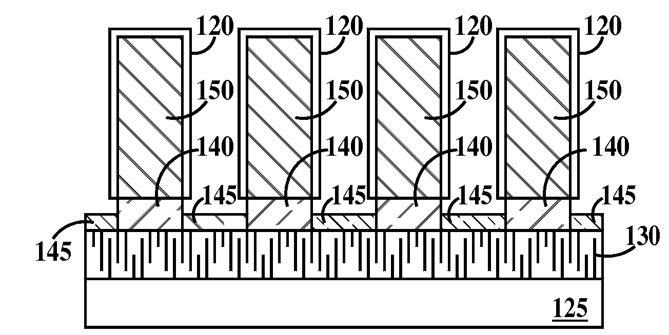
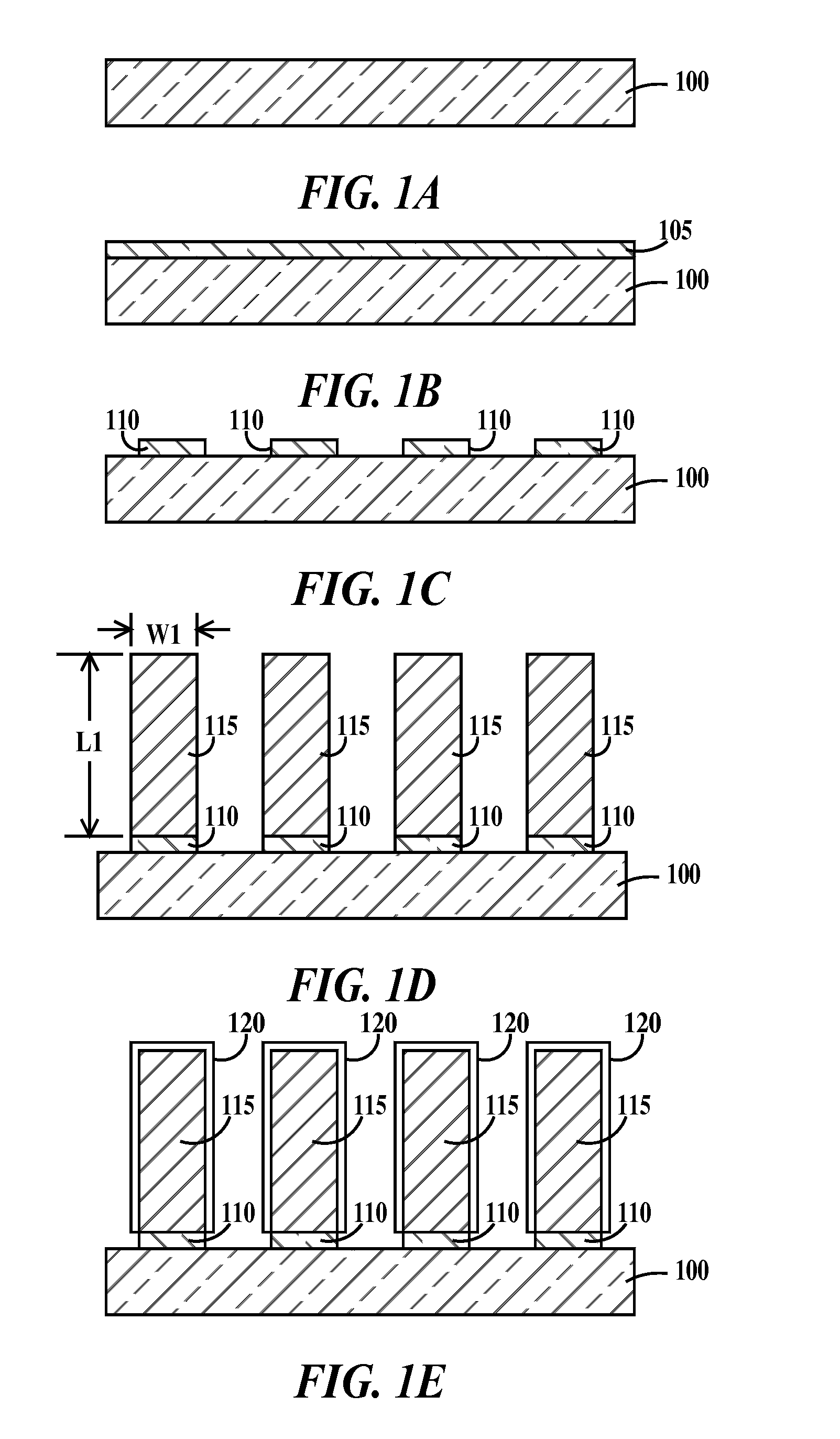
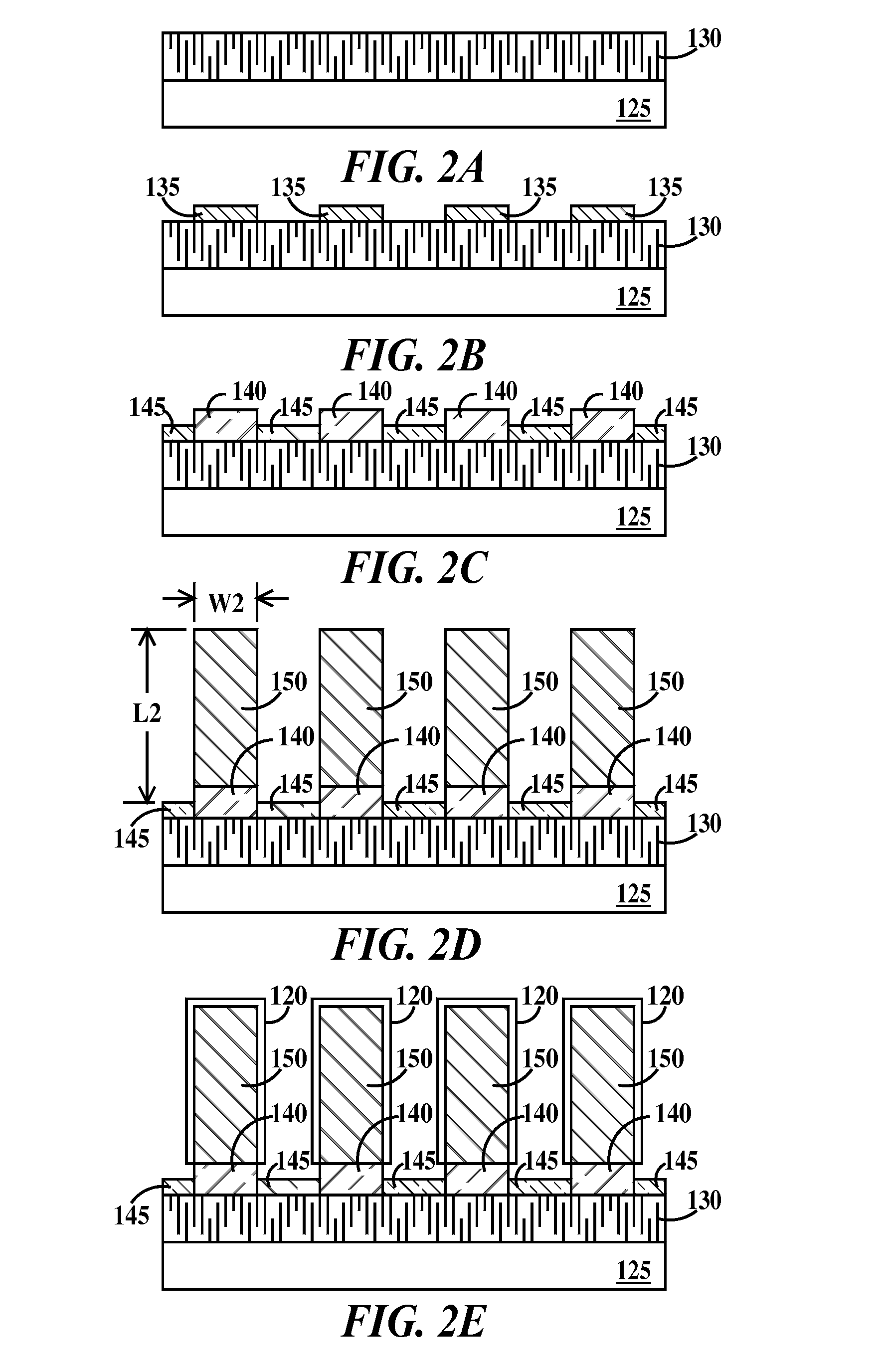
[0027]Carbon nanotubes are more correctly called carbon fullerenes, which are closed-cage molecules composed of sp2-hybridized carbon atoms arranged in hexagons and pentagons. There are two types of carbon fullerenes, namely closed spheroid cage fullerenes also called “bucky balls” and fullerene tubes. Fullerene tubes come in two types, single wall fullerenes tubes, which are hollow tube like structures or and multi-wall fullerene tubes. Multi-wall fullerenes resemble sets of concentric cylinders. The present invention utilizes single-wall carbon fullerenes, hereinafter called single-wall nanotubes (SWNT) and multi-wall carbon fullerenes, hereafter called multi-wall nanotubes (MWNT). For the purposes of the present invention, the term carbon nanotube (CNT) denotes either a carbon SWNT or a carbon MWNT.

[0028]The term chemically active nanotube filter refers to a filter containing carbon nanotubes having a chemically active layer as a filter media or carbon nanotubes having chemically...


PUM

PropertyMeasurementUnit
Flow rateaaaaaaaaaa
Efficiencyaaaaaaaaaa

Abstract

A carbon nanotube filter, a use for a carbon nanotube filter and a method of forming a carbon nanotube filter. The method including (a) providing a carbon source and a carbon nanotube catalyst; (b) growing carbon nanotubes by reacting the carbon source with the nanotube catalyst; (c) forming chemically active carbon nanotubes by forming a chemically active layer on the carbon nanotubes or forming chemically reactive groups on sidewalls of the carbon nanotubes; and (d) placing the chemically active nanotubes in a filter housing.

Description

[0001]This application is a continuation of U.S. patent application Ser. No. 10 / 904,633 filed on Nov. 19, 2004.FIELD OF THE INVENTION[0002]The present invention relates to the field of chemical and particulate filters; more specifically, it relates to chemical and particulate filters containing chemically modified carbon nanotube structures and methods of making same.BACKGROUND OF THE INVENTION[0003]In advanced semiconductor manufacturing, airborne contaminants can cause degradation of photoresist layers and optical elements of advanced photolithography systems such as immersion lithography tools, wherein airborne molecules can polymerize when exposed to the very high energy light beams of advanced lithography tools. The resultant polymer can then coat the optics degrading the image quality of the tool and coat the tooling causing degraded alignment tolerances. Additionally contaminant molecules can be adsorbed by the photoresist layer, interfere with the photochemistry and cause ph...

Claims


Application Information

Patent Timeline
IPC IPC(8): B05D5/02
CPCB01D53/02B01D2253/102B01D2253/304B01J20/20B01J20/205B01J20/3242B82Y30/00Y10S977/742Y10S977/752Y10S977/75Y10S977/748Y10S55/05Y10S977/745
Inventor HOLMES, STEVEN J.HAKEY, MARK C.HORAK, DAVID V.RYAN, JAMES G.
Owner IBM CORP
Why Eureka
Try Eureka