Treating Valvular Insufficiency

a technology for valvular insufficiency and valvular valve, which is applied in the field of valvular insufficiency treatment methods and equipment, can solve the problems of deficiency or failure of valves in the circulatory system such as the tricuspid and mitral heart valves, valve failure, and dilation of the valve annulus, so as to improve the function of the valve, reduce the annulus, and improve the valve function

Inactive Publication Date: 2008-11-20
BAKER MEDICAL RES INST
View PDF46 Cites 129 Cited by
  • Summary
  • Abstract
  • Description
  • Claims
  • Application Information

AI Technical Summary

Benefits of technology

[0012]Briefly, a first aspect of the present invention provides a method of treating valvular insufficiency in a patient. A plurality of filaments is used to engage tissue at spaced apart locations of an annulus of the valve being treated. The engaged filaments are drawn inward so as to draw the engaged tissue inward. The filaments are then secured with the engaged tissue in the drawn-in configuration. Inward drawing of the engaged tissue improves valve function by reducing the valve annulus.
[0013]A second aspect of the present invention provides a valve constriction device for treating valvular insufficiency. The valve constriction device has a plurality of filaments, each having an engaging portion for engaging annular tissue of the valve. A collar is also provided, facilitating a drawn-in configuration of engaged annular tissue by relative movement between the filaments and the collar. Valve function is improved when the engaged filaments are in the drawn-in configuration.
[0014]A third aspect of the present invention provides delivery apparatus for delivering a valve annulus constriction device. The apparatus includes a catheter configured to deliver a plurality of filaments percutaneously to an annulus of the valve being constricted. The catheter is also configured to deliver a collar to be applied over a length of the filaments. Relative movement between the catheter and a filament facilitates positioning of the filament prior to engagement with the valve annulus tissue.
[0015]A fourth aspect of the present invention provides a method of treating valvular insufficiency in a patient in which a plurality of filaments is used to engage tissue at spaced apart locations of an annulus of the valve being treated. The plurality of filaments are then anchored to a region of robust tissue near the valve being treated so as to draw the engaged tissue toward the anchor region thus improving closure of the valve being treated.
[0016]A fifth aspect of the present invention provides a valve constriction device for treating valvular insufficiency which includes a plurality of filaments. Each filament has an engaging portion for engaging annular tissue of the valve. Anchor means is also provided for anchoring the engaged filaments to a region of robust tissue to facilitate drawing of the engaged tissue toward the anchor means to improve leaflet closure.

Problems solved by technology

In some cases, valves in the circulatory system such as the tricuspid and mitral heart valves are deficient or fail.
However, the most common cause of valve failure is dilation of the valve annulus.
The consequences of heart valve failure can vary depending on the seriousness of the failure, but in most cases the heart's efficiency and the efficiency of the circulatory system is seriously affected and complications often result.
Failure or insufficiency of the heart valves frequently results in mitral / tricuspid valve regurgitation.
In the case of the mitral valve, regurgitation results in back pressure in the lungs, whereas tricuspid valve regurgitation can result in high back pressures in the venous circulation.
Clearly, this is undesirable for the health of the heart, as well as for the lungs and other organs of the body.
Mitral and tricuspid valve failure can lead to ineffective and / or inefficient cardiac pumping, ventricular and atrial enlargement, pulmonary and / or circulatory hypertension, heart failure and in some cases, death.
Concomitant with the seriousness of such procedures are an increase in morbidity and mortality risk, and a slow and painful period of rehabilitation which follows.
The location of the tricuspid valve in the right heart complicates treatment because it is less easily accessible than the mitral valve, and it has a more complex triple-leaved structure.
However, unlike the CS / GCV, this vessel is small, variable in size and absent in approximately 50% of cases.
Therefore, reasonable vascular access to the tricuspid annulus is limited to a right atrial approach.
In the past, implications of tricuspid valve regurgitation have not been well understood, and this has only become a topic of interest in recent times. Because of this, the treatment options available for patients experiencing tricuspid valve regurgitation are limited.
Currently available forms of treatment for patients experiencing mitral and tricuspid valve insufficiency are high risk, expensive and prone to complications.

Method used


Image

  • Treating Valvular Insufficiency
  • Treating Valvular Insufficiency
  • Treating Valvular Insufficiency

Examples


Embodiment Construction

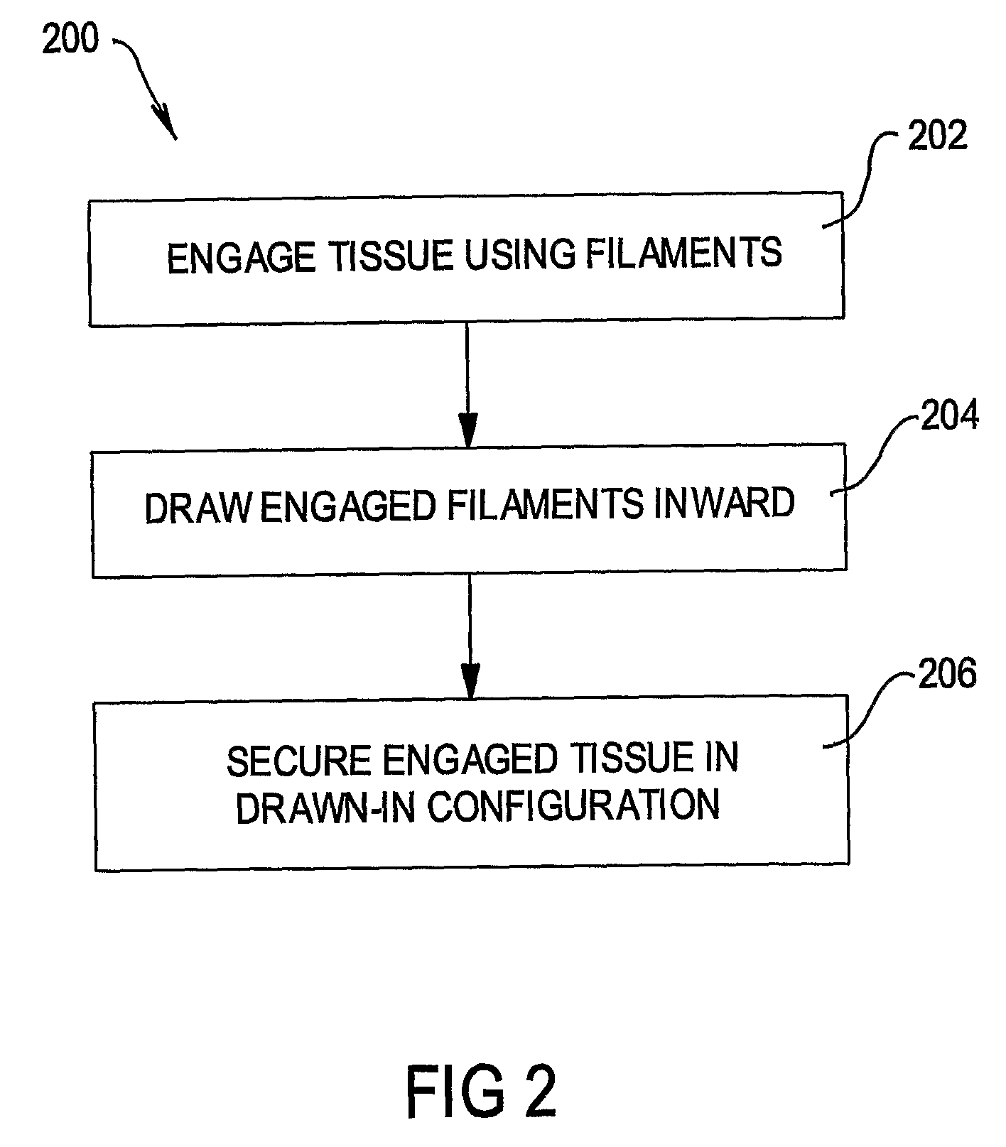
[0026]Referring firstly to FIG. 2, there is shown a method, generally referred to at 200, for treating valvular insufficiency. In a first step 202, a plurality of filaments is used to engage tissue at spaced apart locations of an annulus of the valve being treated. In a second step 204, the engaged filaments are drawn inward so as to draw the engaged tissue around the valve annulus inward. The engaged filaments are then secured with the engaged tissue in the drawn-in configuration in a third step 206 thereby reducing the effective diameter of the annulus of the valve.

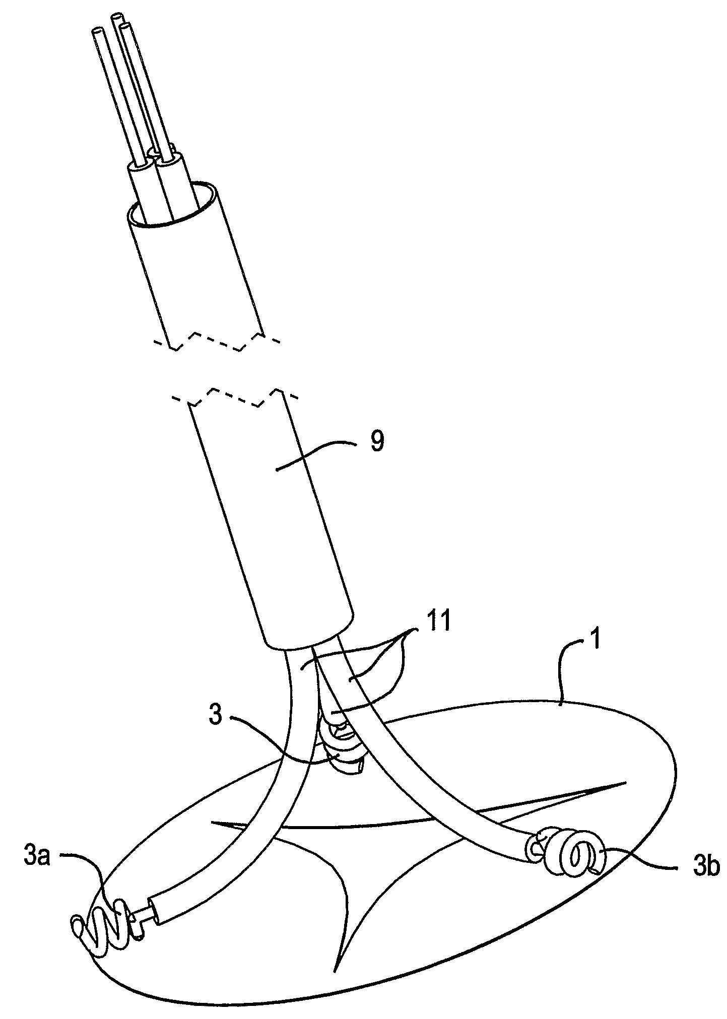
[0027]Referring now to FIGS. 3A and 3B, there is shown a valve constriction device 300 for treating valvular insufficiency according to an embodiment of the invention. A plurality of filaments 2 each have an engaging portion 3 for engaging annular tissue 1 of the valve being treated. A collar 6 facilitates a drawn in configuration of filaments 2 by relative movement between the filaments and the collar. The valve annulu...


PUM


Abstract

In a method of treating valvular insufficiency in a patient, a plurality of filaments (2) are used to engage tissue at spaced apart locations of an annulus (1) of the valve being treated. The engaged filaments (2) are drawn inward so as to draw the engaged tissue around the valve annulus (1) inward. The filaments (2) are then secured with the engaged tissue in the drawn-in configuration. Inward drawing of the engaged tissue improves valve function by reducing the valve annulus (1). Alternatively or additionally, anchor means may be used to secure the filaments to a region of robust tissue, thus drawing the engaged tissue toward the anchor means to further improve valve function.

Description

FIELD OF THE INVENTION[0001]The present invention relates to a method and apparatus for treating valvular insufficiency. In particular, the invention relates to a device and method for treating valvular insufficiency occurring in valves of the heart such as the tricuspid valve, and a delivery apparatus for the same.BACKGROUND TO THE INVENTION[0002]The body's circulation is facilitated by the heart, the cardiac pump which ensures that fresh blood is supplied throughout the body delivering nutrients to organs and transporting waste products to the body's filtration systems. The heart, simplified and illustrated in cross section in FIG. 1, is a complex organ operating two pumping systems. One pumping system includes the left ventricle (LV) and left atrium (LA) and services the systemic circulation in which oxygenated blood is supplied to the body's organs. Deoxygenated blood is then returned to the right heart. The other pumping system includes the right ventricle (RV) and right atrium...

Claims


Application Information

Patent Timeline
Patent Type & Authority Applications(United States)
IPC IPC(8): A61F2/24
CPCA61B17/0401A61B17/0487A61B17/064A61B17/068A61B17/221A61B2017/00243A61B2017/0409A61B2017/0441A61B2017/0445A61B2017/0448A61B2017/0453A61B2017/0458A61B2017/0464A61B2017/0496A61B2017/0649A61B2017/081A61B2017/2215A61F2/2445
Inventor KAYE, DAVID MARTINPOWER, JOHN MELMOUTHALFERNESS, CLIFTON A.BILNEY, ADAM LUCASMATHIS, MARK L.
Owner BAKER MEDICAL RES INST
Why Eureka
Try Eureka