Maintaining consistency within a federation infrastructure

a technology of federation infrastructure and consistency, applied in the direction of transmission, error detection/correction, instruments, etc., can solve the problems of not providing a developer with all the functionality that is needed in an application, dns is not sufficiently dynamic, and can be difficult to access network resources

Inactive Publication Date: 2008-11-20
MICROSOFT TECH LICENSING LLC
View PDF19 Cites 134 Cited by
  • Summary
  • Abstract
  • Description
  • Claims
  • Application Information

AI Technical Summary

Benefits of technology

[0017]This Summary is provided to introduce a selection of concepts in a simplified form that are further described below in the Detailed Description. This Summary is not intended to identify key features or essential features of the claimed subject matter, nor is it intended to be used as an aid in determining the scope of the claimed subject matter.

Problems solved by technology

However, accessing a network resource can be difficult if a computer system has no prior knowledge of a network address for a network resource.
Each different mechanism may have different coding requirements and may not provide a developer with all the functionality that is needed in an application.
For example, although DNS has a distributed administration architecture (i.e., centralized management is not required), DNS is not sufficiently dynamic, not self-organizing, supports a weak data and query model, and has a fixed set of roots.
Further, aspects of different mechanisms may not be compatible with one another.
For example, a resource identified using DNS may not be compatible with DFS routing protocols.
Thus, a developer may be forced to choose the most suitable mechanism and forgo the advantages of other mechanisms.
Mechanisms for identifying resources can be particularly problematic in peer-to-peer networks.
On larger scale networks where nodes frequently connect and disconnect form the network relying on entry of information is not always practical.
Additionally, DNS is specialized to the task of find hosts or services and is not generally applicable to other types of resources.
Further, since IDs (for at least some of the mechanisms) can be uniformly distributed around a ring, there is always some possibility that routing between nodes on the ring will result in some inefficiency.
Additionally, when message routing involves multiple hops, there is some chance that such events will occur multiple times. Unfortunately, these mechanisms do not take into account the proximity of nodes (physical or otherwise) with respect one another.
Unfortunately, these existing mechanisms typically do not provide for, among other things, symmetric relationships between nodes (i.e., if a first node considers a second node to be its partner, the second node considers the first node as a partner as well), routing messages in both directions (clockwise and counterclockwise) on a ring, partitioning linked lists of nodes based on a plurality of proximity metrics, and routing messages based on a plurality of proximity metrics.
These deficiencies can limit dynamic, distributed, and efficient transfer of data between nodes of a network, such as, for example, when broadcasting data to all nodes of the network.
Unfortunately, many existing asynchronous systems provide only limited safety and liveness mechanisms.
For example, some asynchronous systems provide only eventually safety and liveness.
Thus, these asynchronous systems are not suitable for various types of applications, such as, for example, authoritative storage.

Method used


Image

  • Maintaining consistency within a federation infrastructure
  • Maintaining consistency within a federation infrastructure
  • Maintaining consistency within a federation infrastructure

Examples


case 1

[0188] X.id>Y.id[0189]Y.s=X,Y.p=X.p, X.p.s=Y, and X.p=Y

case 2

[0190] X.id[0191]Y.p=X, Y.s=X.s, X.s.p=Y, and X.s=Y

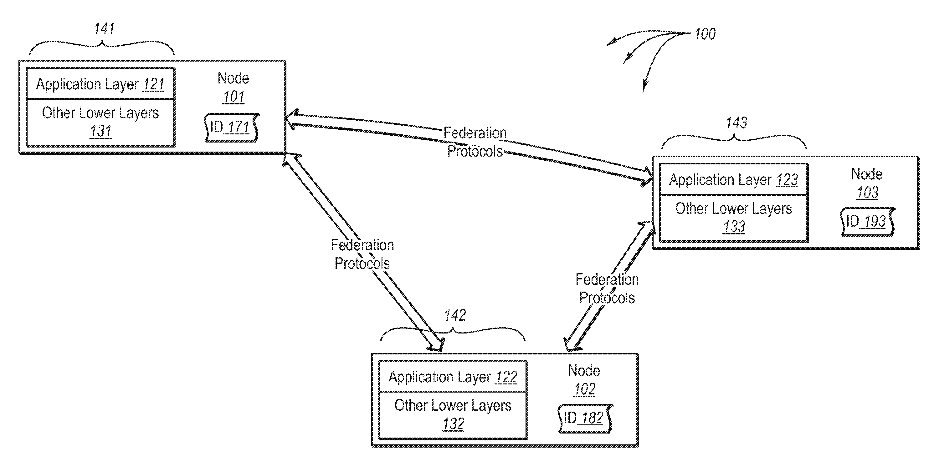
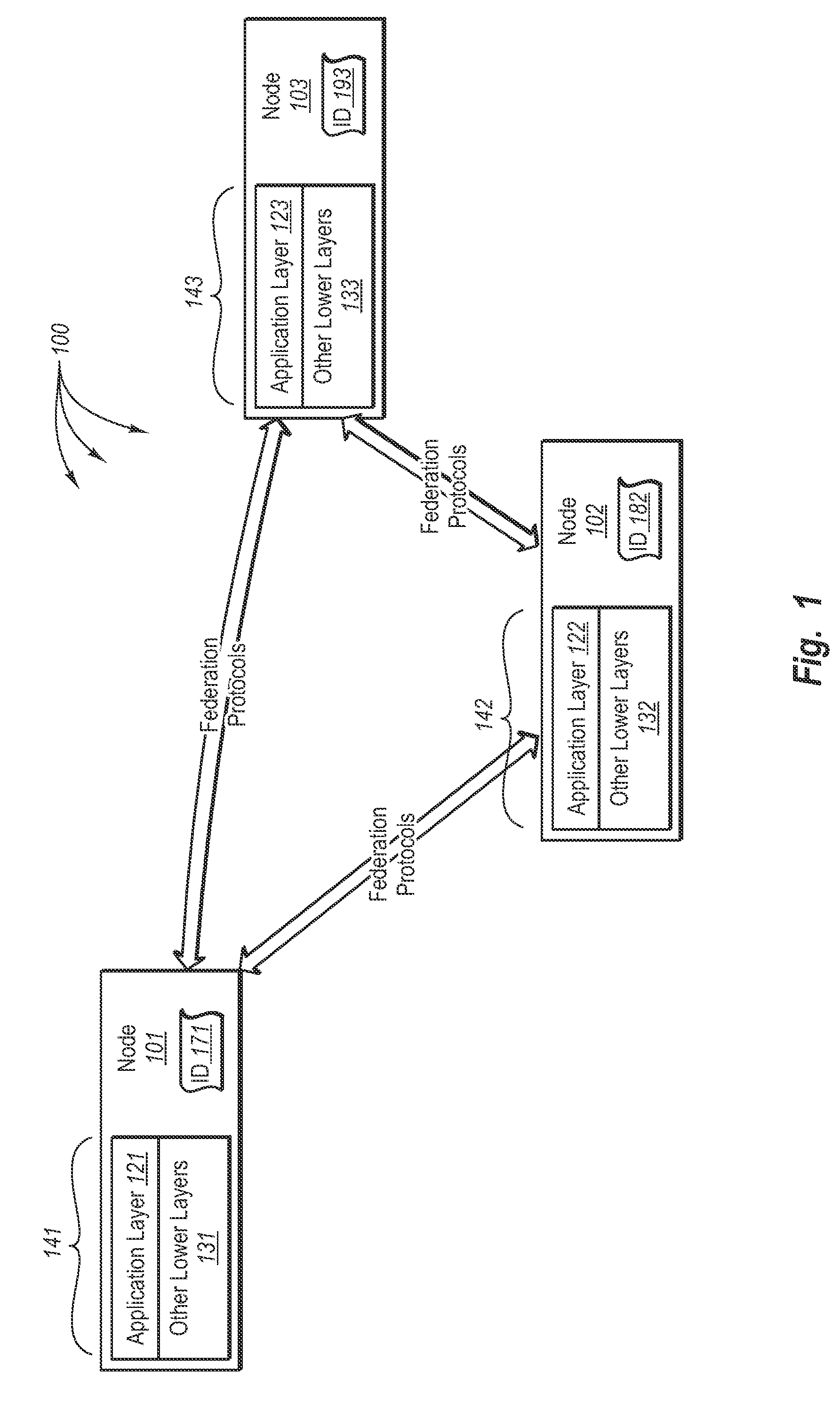
[0192]In response to the join message, node X (the node that processed the join message) can send a join response back to node Y. The join response can indicate the predecessor node (Y.p) and successor node (Y.s) for node Y. Node Y can receive the join response and process the join response to become aware of its predecessor and successor nodes. After processing the join response, Node Y can be a weak routing participant in the federation. For example, Node Y can simply forward message sent to it, either to its successor or predecessor nodes. Thus, Node Y is inserted into the federation infrastructure but routing and neighborhood tables are not populated. Before reaching this point, node Y will request other nodes sending it messages to redirect the messages sent to it through a different node by returning a status message to the sending node indicating that node Y's liveness phase is in an inserting phase-state.

[0193]Generally, fro...


PUM


Abstract

The present invention extends to methods, systems, and computer program products for a joining node to join a ring of nodes within a rendezvous federation. Embodiments include detecting a neighborhood of nodes on the ring of nodes. The joining node indicates its intent to take id-space ownership for a portion of the id-space between the joining node and a selected immediately adjacent node. The joining node indicates an intent to monitor the selected node. The joining node receives three indications, the first indicating acceptance of the joining node's intent to take id-space ownership for a portion of the id-space between the joining node and the selected node, the second indicating acceptance of the joining node's intent to monitor the selected node, the third indicating the first selected node's intent to monitor the joining node. The joining node indicates acceptance of the selected node's intent to monitor the joining node.

Description

CROSS-REFERENCE TO RELATED APPLICATIONS[0001]This application claims the benefit of U.S. Provisional Application No. 60 / 865,136 entitled “P2P Ring of Storage” filed on Nov. 9, 2006.BACKGROUND1. Background and Relevant Art[0002]Computer systems and related technology affect many aspects of society. Indeed, the computer system's ability to process information has transformed the way we live and work. Computer systems now commonly perform a host of tasks (e.g., word processing, scheduling, and database management) that prior to the advent of the computer system were performed manually. More recently, computer systems have been coupled to one another and to other electronic devices to form both wired and wireless computer networks over which the computer systems and other electronic devices can transfer electronic data. As a result, many tasks performed at a computer system (e.g., voice communication, accessing electronic mail, controlling home electronics, Web browsing, and printing do...

Claims


Application Information

Patent Timeline
Patent Type & Authority Applications(United States)
IPC IPC(8): G06F15/173H04L45/586
CPCH04L67/1095G06F17/30215G06F11/1425G06F17/30578H04L67/104H04L67/1046G06F15/16G06F12/00G06F3/06G06F16/273G06F16/1844
Inventor HASHA, RICHARD L.XUN, LUKAKIVAYA, GOPALA KRISHNA R.MALKHI, DAHLIA
Owner MICROSOFT TECH LICENSING LLC
Why Eureka
Try Eureka