

Sheave for Use in an Elevator System
a technology for elevator systems and sheaves, applied in elevators, mine lifts, transportation and packaging, etc., can solve the problems of relative speed differences, noise introduction between the sheave and the load bearing member, etc., and achieve the effect of reducing friction
- Summary
- Abstract
- Description
- Claims
- Application Information
AI Technical Summary
Benefits of technology
Problems solved by technology
Method used
Image

Examples
Embodiment Construction
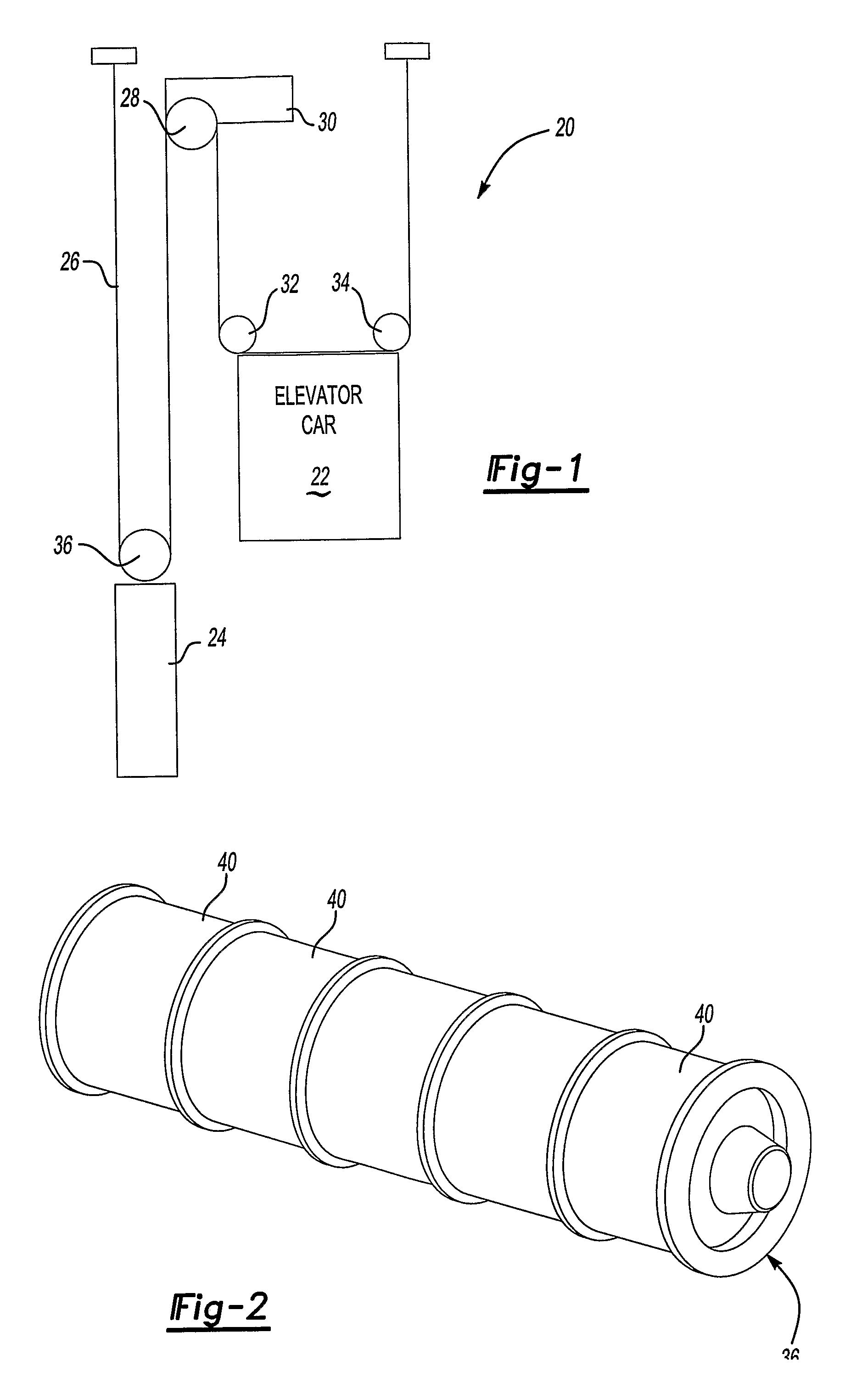
[0014]FIG. 1 schematically shows an elevator system 20 including an elevator car 22 and counterweight 24. Load bearing members 26 support the weight of the car 22 and the counterweight 24 in a known manner. In one example, the load bearing members 26 comprises a plurality of flat belts. This invention is not necessarily limited to any particular roping arrangement nor any particular load bearing member configuration.
[0015]A traction sheave 28 propels the load bearing members 26 to cause desired movement of the elevator car 22 and counterweight 24 responsive to operation of a machine 30 in a known manner.
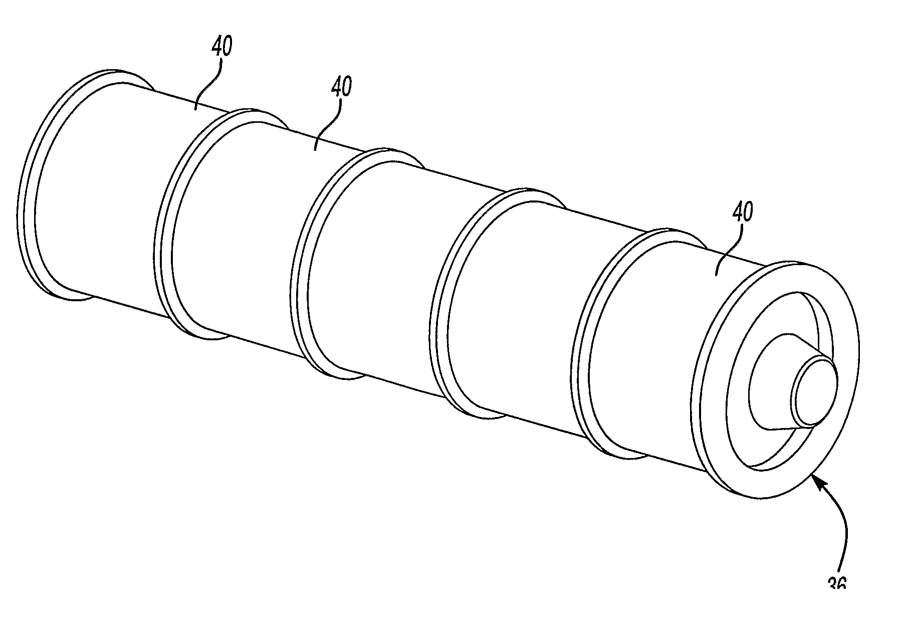
[0016]The illustrated example includes a plurality of deflector or idler sheaves 32 and 34 associated with the elevator car 22. Another idler sheave 36 is associated with the counterweight 24. As known, idler sheaves guide or direct the load bearing members 26 in a selected pattern or direction as the load bearing members 26 move responsive to movement of the traction sheave 28.
[0017...
PUM
 Abstract
Description
Claims
Application Information