
Transmit-mode phased array coils for reduced SAR and artifact issues

Inactive Publication Date: 2008-11-27
BAYER HEALTHCARE LLC
View PDF26 Cites 36 Cited by
  • Summary
  • Abstract
  • Description
  • Claims
  • Application Information

AI Technical Summary

Benefits of technology

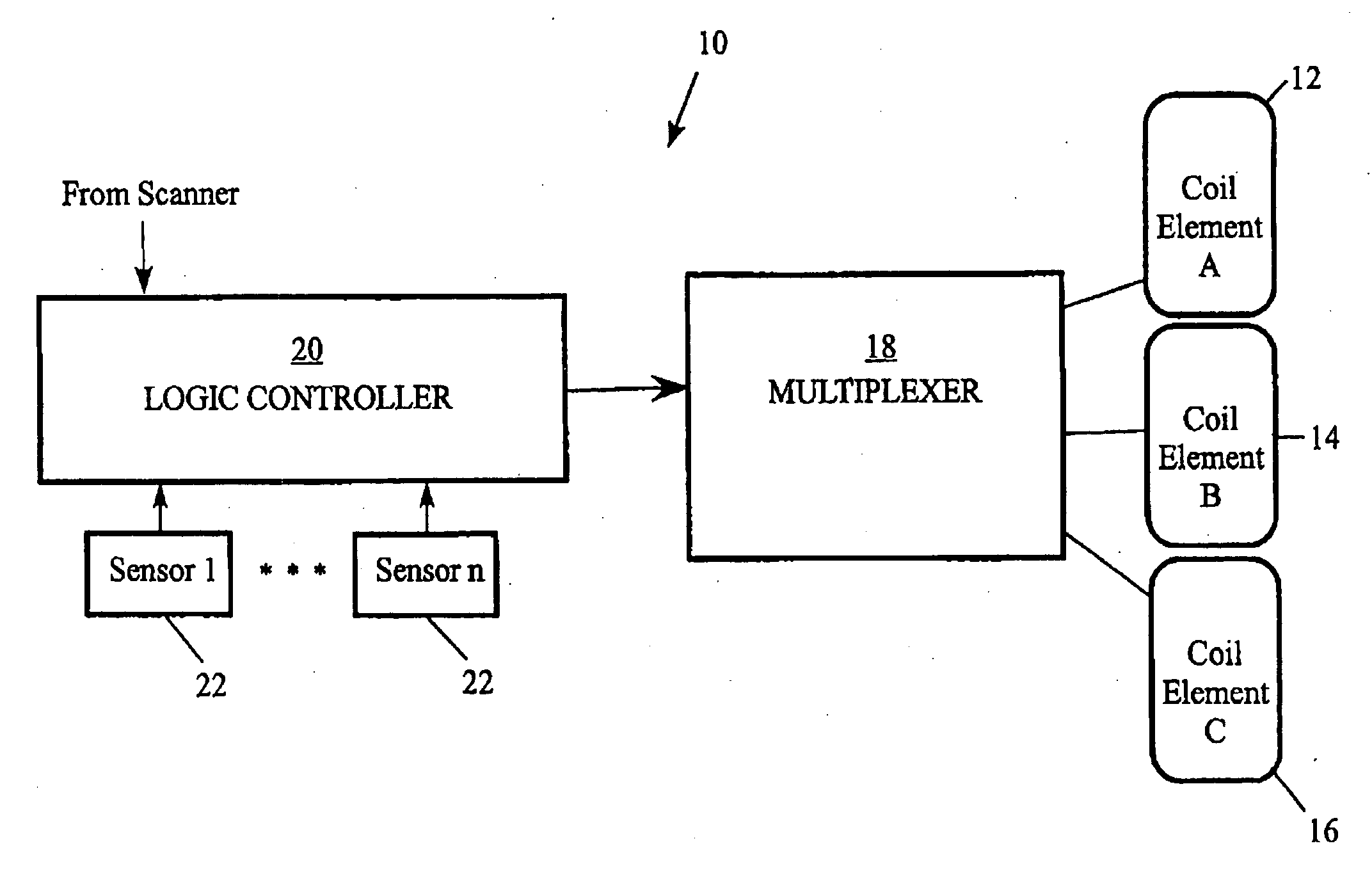
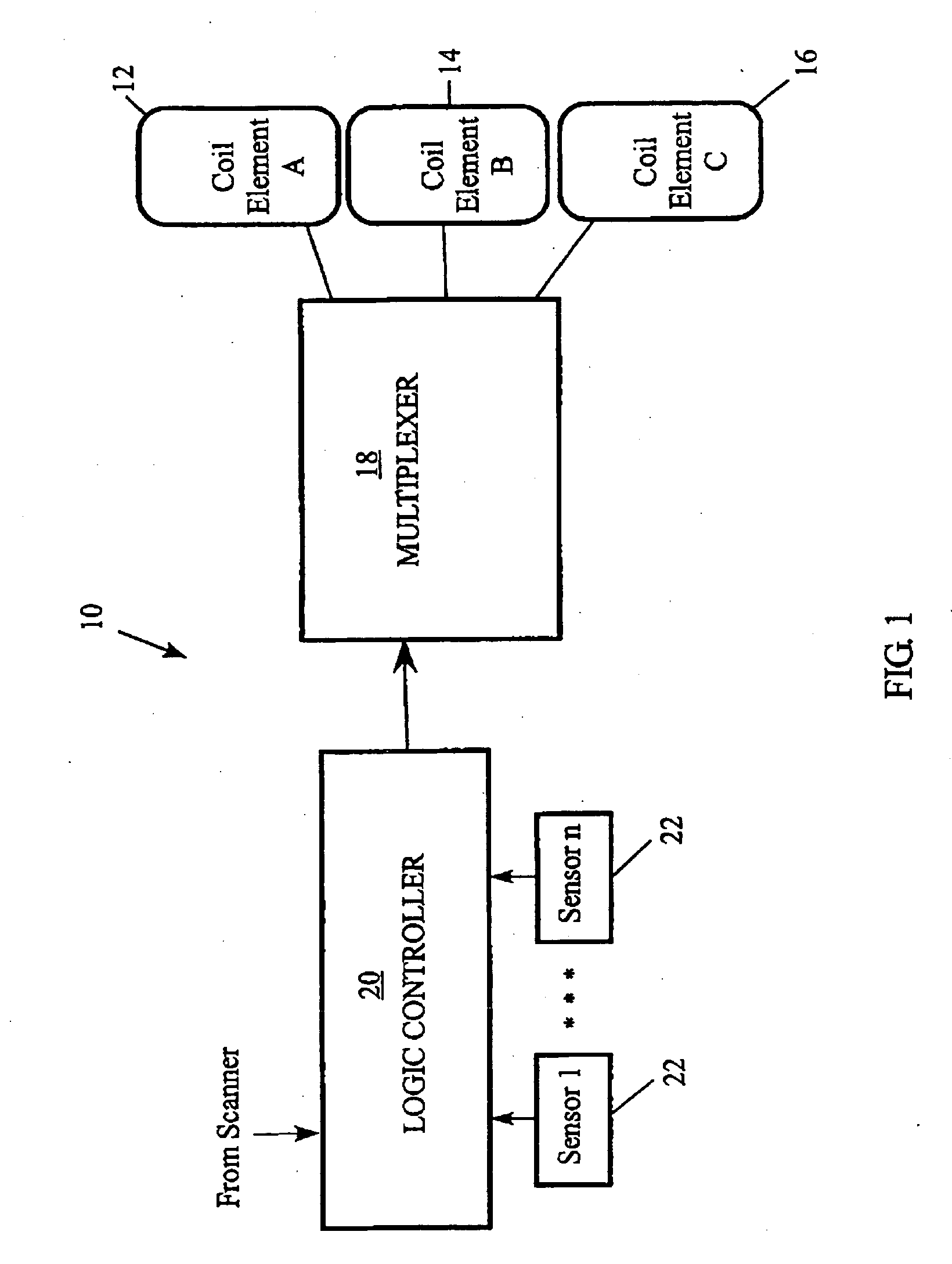
[0015]In accordance with at least one preferred embodiment, the present invention provides systems and methods for a coil system utilizing intelligent transmit mode phased array coil elements. Based on a variety of different inputs from an MR scanner or external sensors, the coil system automatically selects appropriate transmit (and receive) coil elements from a plurality of existing coil elements in order to supply RF power from the MR scanner to only those transmit coil elements that are required for a particular scan or mode (or portion of a scan). The system reduces SAR, prevents many potential artifact problems and provides a more uniform RF transmit field because power is only applied where needed.

Problems solved by technology

In the use of RF coils, there is a continual tension between transmission power, reception fidelity and a wide range of electromechanical problems (e.g., image artifacts and heightened patient specific absorption rate (SAR) levels).
Due to their large volume, however, whole body receive coils suffer from a relative insensitivity to individual spins.
A disadvantage of local coils, especially local surface coils, however, is their limited reception area or field of view (FOV).
Therefore, surface coils necessarily restrict the field of view, and inevitably lead to a tradeoff between the resolution of the gathered data (and the resulting image) and the field of view.
Generally, large surface coils generate more noise due to their exposure to greater patient sample losses and therefore have a larger noise component relative to the signal, while smaller coils have lower noise but in turn restrict the field of view to a smaller region.
In much the same way, the transmission of RF power to a patient's body has caused similar problems in the art.
Any RF power that is transmitted to an area of the patient other than the intended region of interest is wasted (at least) and may cause problems for the patient or the resulting image of the patient.
Moreover, although MRI procedures are extremely safe, it may not always be preferred to send RF power into non-ROI portions of a patient (increased SAR).
Devices and methods to allow for the selection of only some of the plurality of coil elements in an array coil system at different times during a scan have been suggested, but no acceptable solution to this problem has heretofore been provided.
These prior systems are not useful across a wide variety of existing MR scanners and instead require a specifically-designed scanner for operation.

Method used


Image

  • Transmit-mode phased array coils for reduced SAR and artifact issues
  • Transmit-mode phased array coils for reduced SAR and artifact issues
  • Transmit-mode phased array coils for reduced SAR and artifact issues

Examples


Embodiment Construction

[0028]It is to be understood that the figures and descriptions of the present invention have been simplified to illustrate elements that are relevant for a clear understanding of the invention, while eliminating, for purposes of clarity, other elements that may be well known. Those of ordinary skill in the art will recognize that other elements are desirable and / or required in order to implement the present invention. However, because such elements are well known in the art, and because they do not facilitate a better understanding of the present invention, a discussion of such elements is not provided herein. The detailed description will be provided hereinbelow with reference to the attached drawings.

[0029]The present invention, in at least one embodiment, provides for the use of a group of coil elements in an array fashion for the transmit-mode excitation of the spin systems during MR imaging and / or spectroscopy. The transmit coil system comprises a number of coil elements with e...


PUM


Abstract

Systems and methods for the selection of and application of RF power to a plurality of transmit and / or transmit / receive coil elements to decrease patient SAR and to limit the potential for artifact problems. Without any change to the hardware or software of an MR scanner, the present local coil system provides system logic and coil design flexibility such that only transmit coil elements that are required for a particular portion of an MR scan will be utilized at that time. The local coil system may include any combination of transmit-only, receive-only and transmit / receive coil elements as part of the coil system (array of coil elements). The logic controller of the local coil system gathers input data from the MR scanner, from the attached coil elements and optionally from one or more sensors attached to the coil system itself.

Description

BACKGROUND OF THE INVENTION[0001]1. Field of the Invention[0002]The present invention generally relates to magnetic resonance imaging (“MR” or “MRI”) and, more particularly, to devices and methods for selectively enabling transmit and transmit / receive RF coil elements for use with an MRI host device.[0003]2. Description of the Background[0004]MRI systems, and the coils for use therewith, have changed dramatically since the inception of the science in the 1970's. As MR scanners become more powerful and have stronger magnetic fields, the RF coils used to transmit RF signals to the patient and receive a response therefrom have become more precise and better able to achieve a variety of different scan modes. In the use of RF coils, there is a continual tension between transmission power, reception fidelity and a wide range of electromechanical problems (e.g., image artifacts and heightened patient specific absorption rate (SAR) levels).[0005]Initially, MRI systems used large, whole body...

Claims


Application Information

Patent Timeline
IPC IPC(8): G01R33/20
CPCG01R33/288G01R33/3415
Inventor MISIC, GEORGE
Owner BAYER HEALTHCARE LLC
Learn More