Projection optical system, exposing method, exposure apparatus, and device fabricating method

a technology of projection optical system and exposure apparatus, which is applied in the direction of photomechanical treatment, printing, instruments, etc., can solve the problems of deteriorating the projection state of the image of the pattern, the change in the radiation state of the exposure light with respect to the substrate, and the increase of the exposure apparatus

Inactive Publication Date: 2008-11-27
NIKON CORP
View PDF11 Cites 3 Cited by
  • Summary
  • Abstract
  • Description
  • Claims
  • Application Information

AI Technical Summary

Benefits of technology

[0010]According to the first aspect of the invention, it is possible to prevent an increase in the size of the members that are disposed close to the optical element of the projection optical system.
[0023]According to some aspects of the present invention, it is possible to expose a substrate through a liquid satisfactorily, and thereby to fabricate a device that has a desired performance specification.

Problems solved by technology

If the sizes of the members that are disposed in the vicinity of the optical element increase, then there is a possibility that the overall size of the exposure apparatus will increase.
If the physical properties of the liquid change, then there is a possibility that the radiation state of the exposure light with respect to the substrate will change, and that the projection state of the image of the pattern will deteriorate.

Method used


Image

  • Projection optical system, exposing method, exposure apparatus, and device fabricating method
  • Projection optical system, exposing method, exposure apparatus, and device fabricating method
  • Projection optical system, exposing method, exposure apparatus, and device fabricating method

Examples


first embodiment

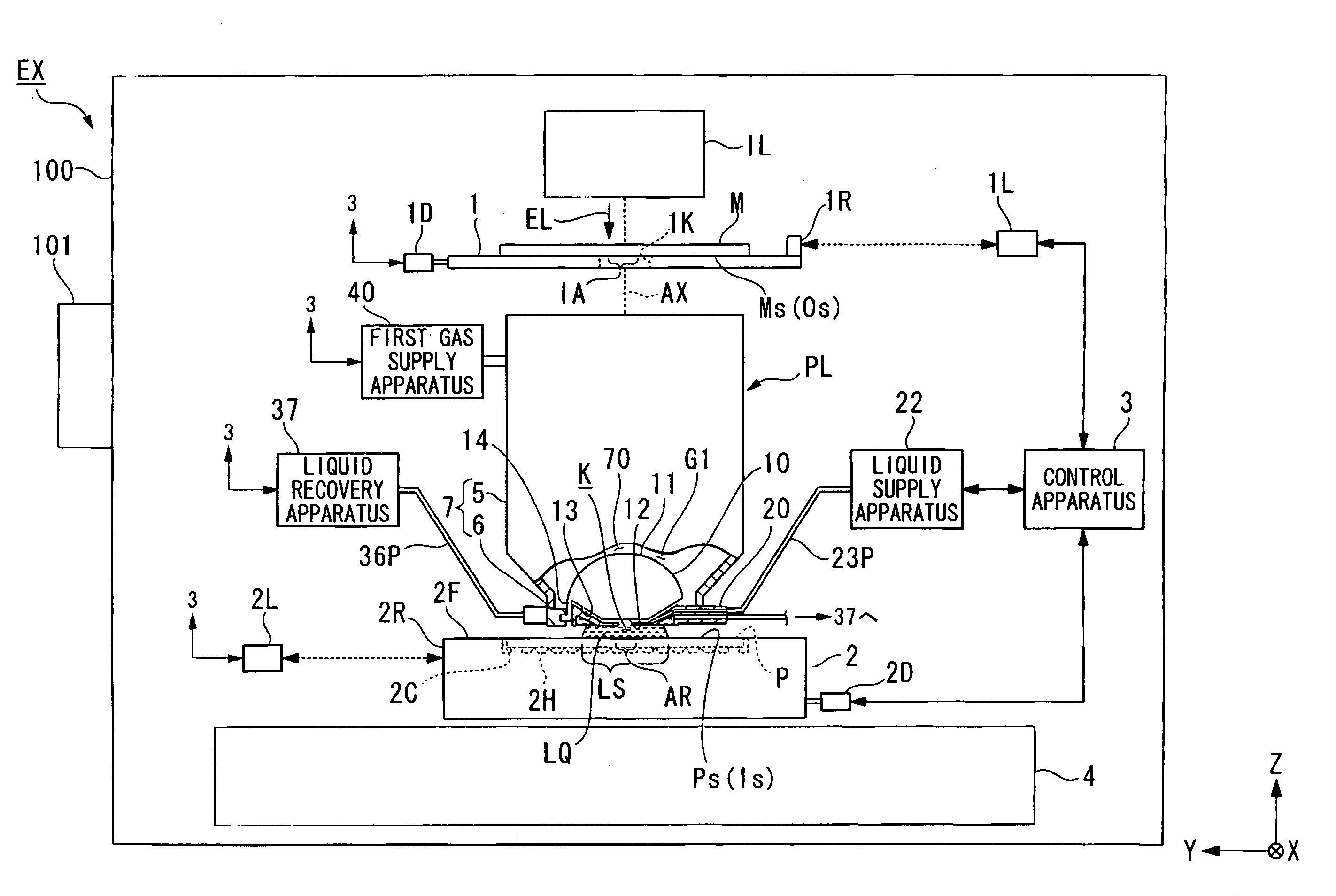
[0040]A first embodiment will now be explained. FIG. 1 is a schematic block diagram that shows an exposure apparatus EX according to the first embodiment. In FIG. 1, the exposure apparatus EX comprises a movable mask stage 1 that holds a mask M, a movable substrate stage 2 that holds a substrate P, an illumination system IL that illuminates a pattern of the mask M with exposure light EL, a projection optical system PL that projects an image of the pattern of the mask M, which is illuminated by the exposure light EL, onto the substrate P, and a control apparatus 3 that controls the operation of the entire exposure apparatus EX. Furthermore, the substrate P described herein includes one wherein films, for example, a protective film and a film of a photosensitive material (photoresist) are coated on a base material, such as a semiconductor wafer. The mask M includes a reticle wherein a device pattern is formed that is reduction projected onto the substrate P. The projection optical sys...

second embodiment

[0105]The following explains a second embodiment. A characteristic feature of the second embodiment is that it provides a second gas supply port, which supplies the gas to at least part of the gas space 71, which surrounds the immersion space LS. In the explanation below, constituent parts that are identical or equivalent to those in the embodiment discussed above are assigned identical symbols, and the explanations thereof are therefore abbreviated or omitted.

[0106]FIG. 8 is an enlarged cross sectional view of part of the exposure apparatus EX according to the second embodiment. In the present embodiment, the same as in the first embodiment discussed above, the exposure apparatus EX comprises the gas passageway 42 that communicates with prescribed space 70 and the gas space 71, which surrounds the immersion space LS, so that the gas G1 that is supplied via the first gas supply port 41 contacts the liquid LQ of the immersion space LS. In the present embodiment, the exposure apparatu...

third embodiment

[0115]The following explains a third embodiment. The characteristic feature of the third embodiment is that it provides an exhaust port (suction port) for discharging (suctioning) the gas that flows from the prescribed space 70 on the incident surface 11 of the optical element 10 into the gas space 71, which surrounds the immersion space LS. In the explanation below, constituent parts that are identical or equivalent to those in the embodiments discussed above are assigned identical symbols, and the explanations thereof are therefore abbreviated or omitted.

[0116]FIG. 9 is an oblique view that shows the vicinity of the optical element 10 according to the third embodiment, FIG. 10 is an oblique view of FIG. 9, viewed from the −Z side, and FIG. 11 is a side cross sectional view that shows the vicinity of the optical element 10. As shown in FIG. 9, FIG. 10, and FIG. 11, the exposure apparatus EX according to the third embodiment, similar to the first embodiment discussed above, comprise...


PUM


Abstract

A projection optical system projects an image of a first surface to a second surface through a liquid. The projection optical system comprises an optical element, wherein the first surface side contacts a gas and the second surface side contacts the liquid. The optical element has an incident surface, which is convex toward the first surface, an emergent surface, an outer circumferential surface between an outer circumference of the incident surface and an outer circumference of the emergent surface, and holding parts, which are formed at a circumferential edge part of the outer circumferential surface so that they project toward the second surface.

Description

CROSS-REFERENCE TO RELATED APPLICATION[0001]This application is a non-provisional application claiming priority to and the benefit of U.S. provisional application No. 60 / 924,545, filed May 18, 2007, and is a Continuation Application of International Application No. PCT / JP2007 / 059982, filed May 15, 2007, which claims priority to Japanese Patent Application No. 2006-136387, filed May 16, 2006.BACKGROUND[0002]1. Field of the Invention[0003]The present invention relates to a projection optical system, an exposing method, an exposure apparatus, and a device fabricating method.[0004]2. Description of Related Art[0005]In photolithography, which is one of the processes in the fabrication of microdevices such as semiconductor devices, an exposure apparatus is used that projects an image of a pattern formed on a mask onto a photosensitive substrate through a projection optical system. In the field of microdevice fabrication, there is demand to increase the fineness of the patterns formed on s...

Claims


Application Information

Patent Timeline
Patent Type & Authority Applications(United States)
IPC IPC(8): G03B27/54G03B27/52
CPCG03F7/70341
Inventor NAGASAKA, HIROYUKI
Owner NIKON CORP
Why Eureka
Try Eureka