
Light emitting device module

a technology of light emitting devices and modules, which is applied in the direction of fixed installation, lighting and heating apparatus, and light support devices, etc., can solve the problems of reduced heat radiation difficult to transfer led heat to the submount, etc., and achieve the effect of improving the heat radiation effect and increasing the size of the light emitting device modul

Inactive Publication Date: 2008-11-27
KOITO MFG CO LTD
View PDF0 Cites 50 Cited by
  • Summary
  • Abstract
  • Description
  • Claims
  • Application Information

AI Technical Summary

Benefits of technology

[0011]It is an aspect of the present invention to provide a light emitting device module, which includes a light emitting device, whose heat radiation effect is improved without increasing the size of the light emitting device module.

Problems solved by technology

In this case, the LED generates heat accompanying the light emission, and thus the LED causes thermal runaway due to this heat, and the light emission characteristic is degraded.
However, since the submount is formed of a high-resistive insulating material in this structure, it becomes difficult to transfer the heat generated by the LED to the submount and also to transfer the heat from the submount to the heat radiating plate.
Therefore, it is difficult to transmit the heat generated by the LEDs to the high heat-radiant substrate at a high efficiency, and as a result the heat radiated is reduced, and it is difficult to improve the heat radiation.
However, this increase in size also increases the overall size of the LED module.
Thus, it is difficult to implement a small-sized light source or a small-sized vehicle lamp.

Method used


Image

  • Light emitting device module
  • Light emitting device module
  • Light emitting device module

Examples


first exemplary embodiment

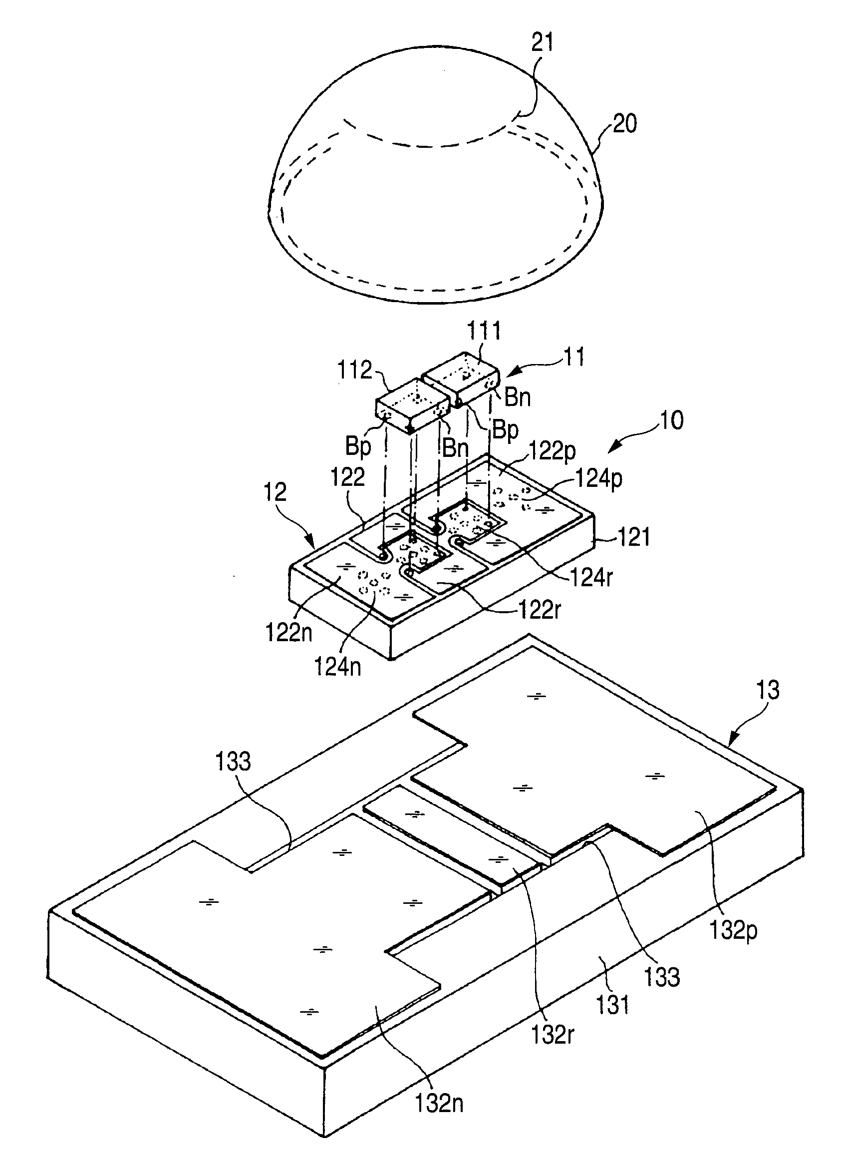
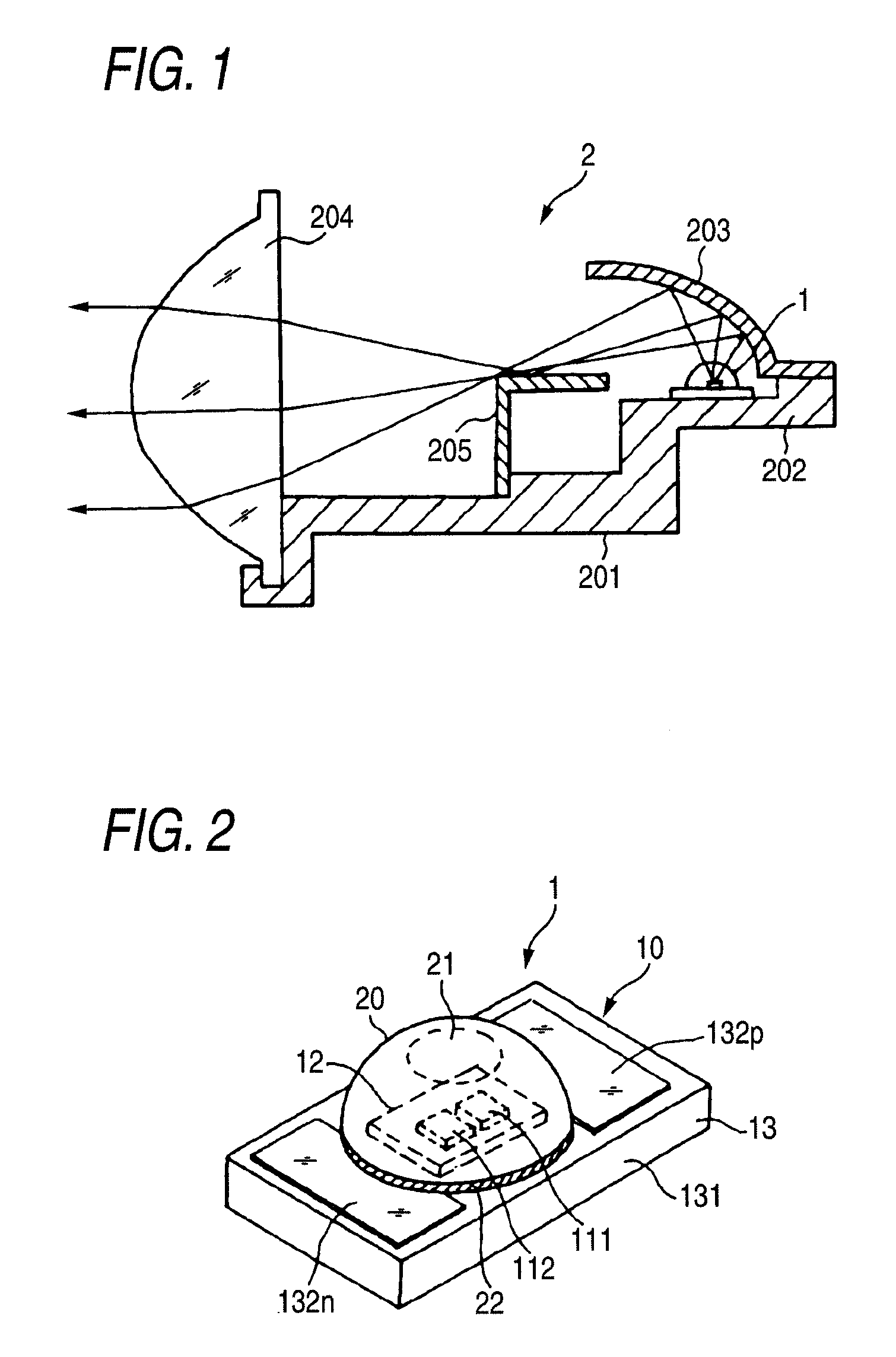
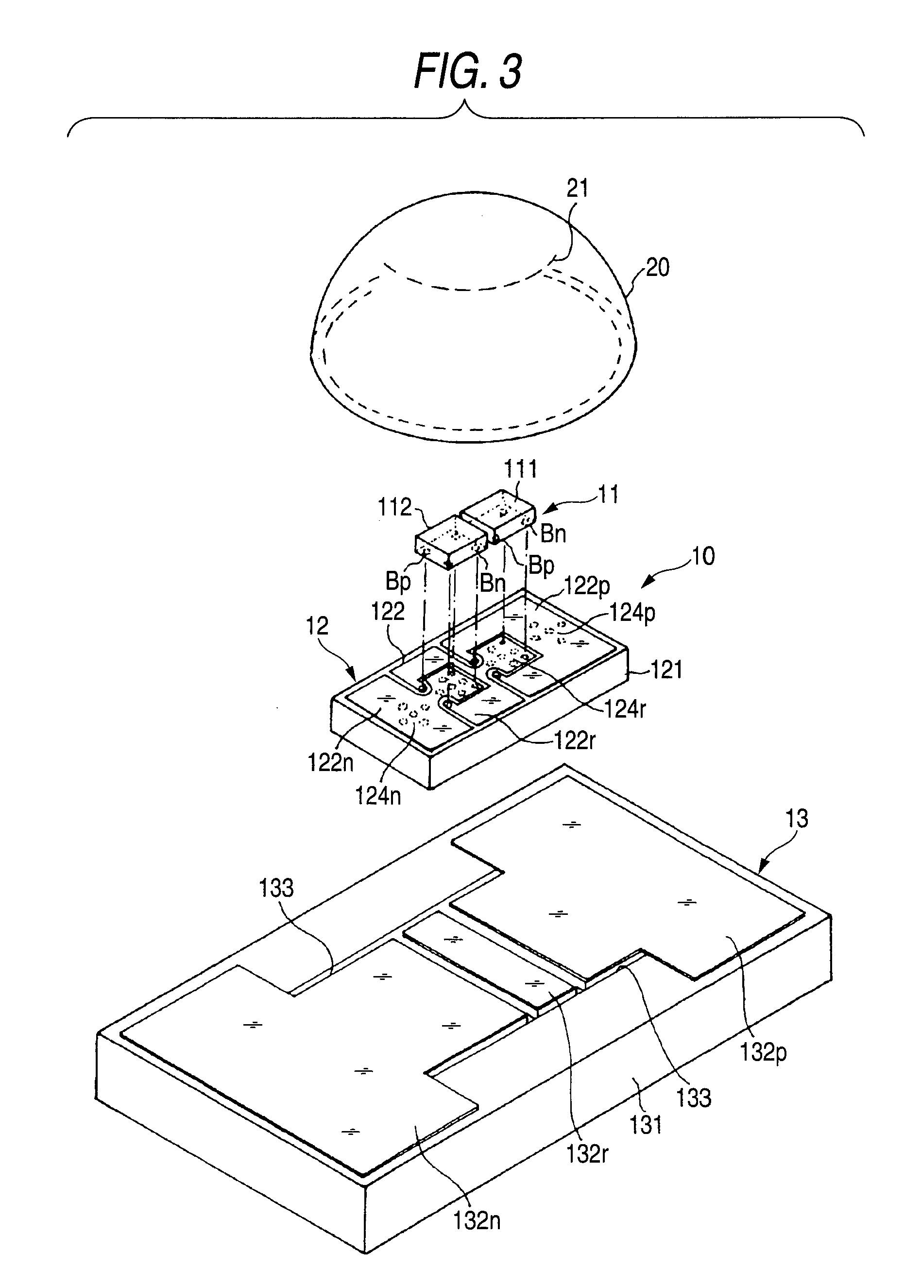
[0024]A first exemplary embodiment will now be described with reference to FIGS. 1-5, in which a light emitting device module is applied to an LED module used as a light source. It should be noted that the light emitting device module according to exemplary embodiments of the present invention often find application in a headlamp of a car. However, the present invention is not limited to this application. Rather, the present inventive concept applies equally to any vehicle headlamp, and to any light emitting device module which has a relatively high luminous intensity and for which it is advantageous to increase the efficiency of heat radiation. FIG. 1 is a schematic sectional view of an LED lamp 2. The LED lamp 2 comprises a base member 201 formed integrally with a heat sink 202, a reflector 203 supported by the heat sink 202 and having a reflecting surface that is curved upwardly like an ellipsoid of revolution, an LED light source 1 mounted on a part of an upper surface of the he...

second exemplary embodiment

[0036]FIG. 6 is a plan view of an LED module 10 according to a second exemplary embodiment of the present invention. In the LED module 10, first to fourth LEDs 111, 112, 113, 114 are used as a light source, and are coupled together in series. FIG. 7 is a sectional view of the LED module 10 according to the second exemplary embodiment. As in FIG. 5, a part of the structure of the LED module 10 is changed in FIG. 7 in order to facilitate illustration. The same reference symbols are affixed to the equivalent portions to those in the first exemplary embodiment. Also, FIGS. 8A and 8B are a front surface view and a back surface view, respectively, of a submount of FIG. 7. In the second exemplary embodiment, the positive and negative surface electrodes 122p, 122n are formed on both ends of the substrate 121 as the front surface electrodes 122 on the surface of the submount 12, and then first to third relay surface electrodes 122r1, 122r2, 122r3 are aligned between the positive and negative...


PUM


Abstract

A light emitting device module is provided. The light emitting device module includes a plurality of light emitting devices; a submount on which the light emitting devices are mounted; and a heat-radiant substrate to which the submount is fixed. The submount includes a positive front surface electrode; a negative front surface electrode; at least one relay front surface electrode, wherein the plurality of light emitting devices are electrically coupled to each other in series via the at least one relay front surface electrode; a plurality of through electrodes; a positive back surface electrode coupled to the positive front surface electrode via a through electrode; a negative back surface electrode coupled to the negative front surface electrode via a through electrode; and at least one relay back surface electrode which is coupled to the at least one relay front surface electrode via a through electrode. The heat-radiant substrate includes a positive circuit electrode bonded to the positive back surface electrode; a negative circuit electrode bonded to the negative back surface electrode; and at least one relay circuit electrode bonded to the at least one relay back surface electrode and being floated electrically.

Description

[0001]This application claims priority from Japanese Patent Application No. 2007-137492, filed on Mar. 24, 2007, the entire contents of which are hereby incorporated by reference.BACKGROUND[0002]1. Technical Field[0003]Apparatuses and devices consistent with the present invention relate to a light emitting device module having a semiconductor light emitting device such as a light emitting diode (LED) and, more particularly, to a light emitting device module for improving heat radiation performance of the light emitting device.[0004]2. Related Art[0005]Recently, a lamp using a light emitting device such as an LED as a light source of the lamp instead of an incandescent lamp or a discharge bulb has been proposed. Previously, an LED has been applied to vehicle tail lamps and the turn signal lamps up to now. However, with the development of a white LED with a high intensity in recent years, the LED has been proposed as a light source for a vehicle headlamp. In this case, the LED generat...

Claims


Application Information

Patent Timeline
IPC IPC(8): F21S8/10H01L33/00F21V7/00H01L33/62H01L33/58H01L33/64
CPCF21K9/00F21S48/1159F21S48/1163F21S48/328F21V29/74F21Y2101/02H01L25/0753H05K1/0206F21V29/004H01L2224/16225H01L2224/14F21Y2115/10F21S41/155F21S45/47F21V29/76F21S41/151F21S41/148
Inventor HIGASHI, YUJI
Owner KOITO MFG CO LTD
Features
  • Generate Ideas
  • Intellectual Property
  • Life Sciences
  • Materials
  • Tech Scout
  • Unparalleled Data Quality
  • Higher Quality Content
  • 60% Fewer Hallucinations
Learn More