
Optical Recording Medium

a recording medium and optical technology, applied in mechanical recording, record information storage, instruments, etc., can solve the problems of jitter value increase and quality degradation of wobble signals

Inactive Publication Date: 2008-11-27
RICOH KK
View PDF12 Cites 2 Cited by
  • Summary
  • Abstract
  • Description
  • Claims
  • Application Information

AI Technical Summary

Benefits of technology

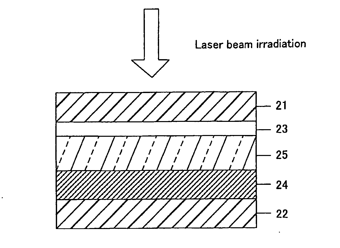
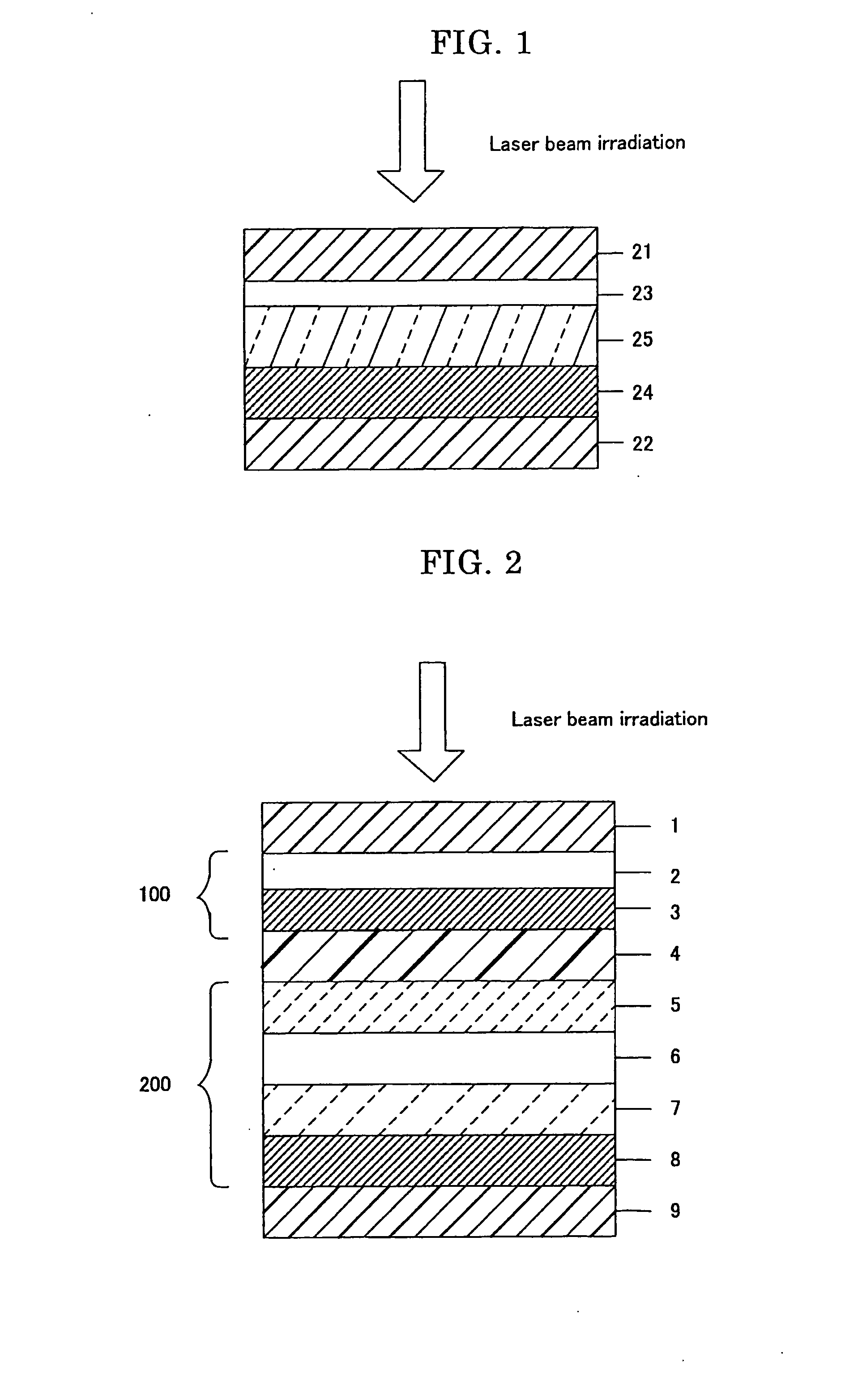
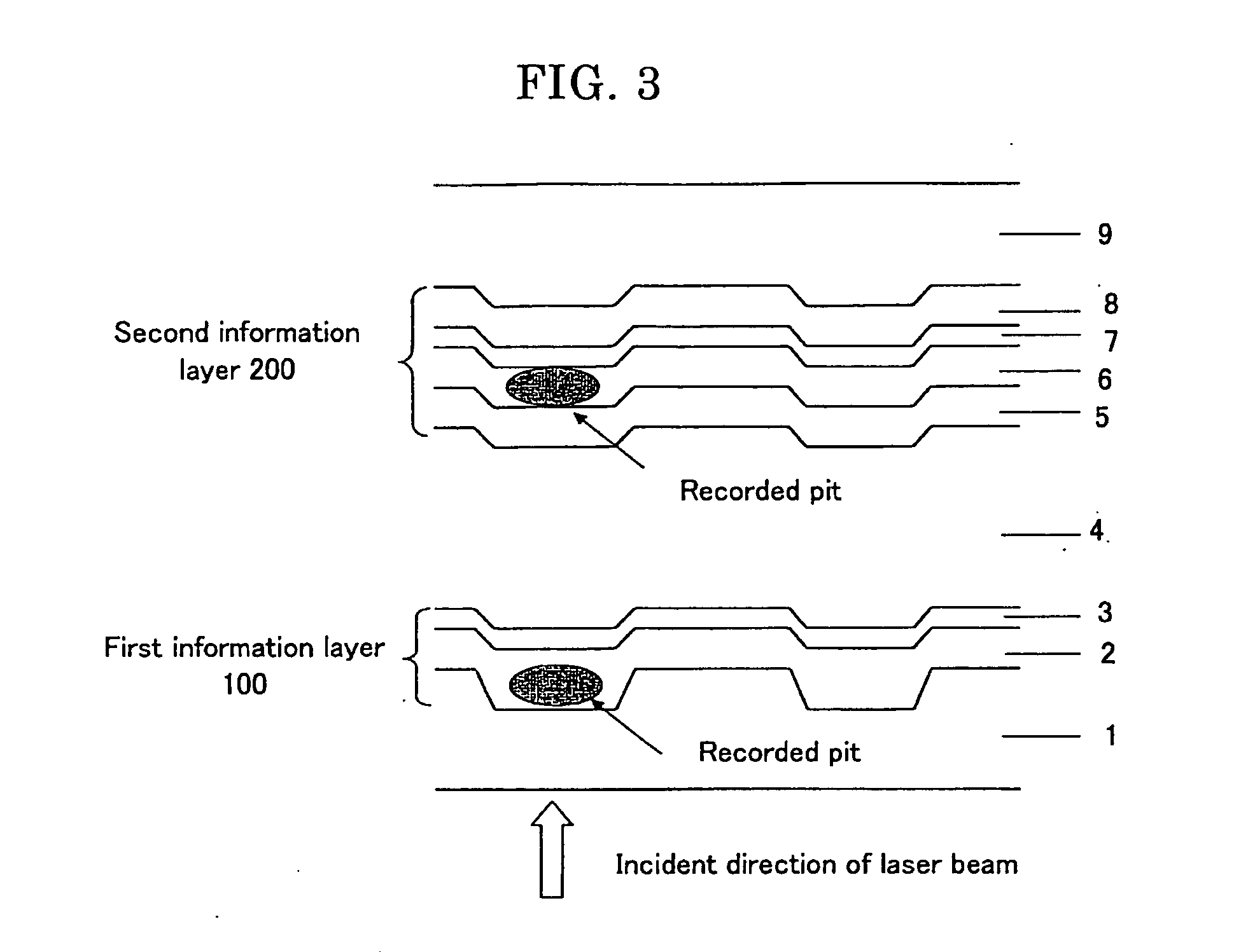
The present invention provides an optical recording medium that can record and play information on both sides of the disc. It solves the problem of heat spreading and degradation of signal quality when recording on concave tracks in conventional optical recording media. The medium includes a first information layer, an intermediate layer, and a second information layer, with the second information layer containing a second dye recording layer, a dielectric layer, and a reflective layer. The dielectric layer can contain materials such as oxides, nitrides, sulfides, carbides, or mixtures thereof. The thickness of the second dye recording layer is thicker than that of the first dye recording layer to prevent deformation of the recording track and improve signal amplitude and reflectance. The medium can be used for recording and playing information on each of the first and second information layers by laser beam irradiation from the first information layer side.

Problems solved by technology

In addition, when information is recorded on consecutive tracks, heat from irradiation of a recording laser beam, and heat generated at the time of decomposition of dye spreads over adjacent tracks, which causes a phenomenon that the jitter value is increased, and the quality of wobble signals degrades, because the thickness of the dye recording layer formed on the convex portions is substantially equal to or slightly thinner than that of the dye recording layer formed on concave portions which are formed between tracks.

Method used


Image

  • Optical Recording Medium
  • Optical Recording Medium
  • Optical Recording Medium

Examples


example

[0069]Hereinafter, the present invention will be further described in detail referring to specific Examples and Comparative Examples, however, the present invention is not limited to the disclosed examples. For example, prepared optical recording media were evaluated under a recording and reproducing condition of a recording linear velocity of 8× DVD (linear velocity=30.6 m / sec), however, when the recording and reproducing condition is changed to further higher speeds, higher-speed recording and reproducing is enabled.


PUM

PropertyMeasurementUnit
melting pointaaaaaaaaaa
thicknessaaaaaaaaaa
thicknessaaaaaaaaaa

Abstract

The object of the present invention is to provide an optical recording medium which includes a substrate, a first information layer and a second information layer, the first information layer and the second information layer are disposed on the substrate through an intermediate layer in a laminar structure; recording and reproducing is performed on each of the two information layers by laser beam irradiation from the first information layer side; the second information layer is provided with at least a reflective layer, a dielectric layer, and a second dye recording layer formed in this order; and the dielectric layer is formed from any one of materials selected from the group consisting of oxides, nitrides, sulfides, carbides or mixtures thereof from any one of elements which are not same as metal elements and semi-metal elements used for forming the reflective layer.

Description

TECHNICAL FIELD[0001]The present invention relates to a recordable optical recording medium on which information can be recorded and reproduced by irradiating the recording layers with an optical beam to induce optical changes in transmittance, reflectance and the like on the recording layers, and the present invention is particularly applicable to two-layered DVD (Digital Video Disc or Digital Versatile Disc).BACKGROUND ART[0002]Recently, in addition to optical recording media such as read-only DVD-ROM (Digital Versatile Disc-Read Only Memory), recordable DVD such as DVD+RW, DVD+R, DVD-R, DVD-RW, and DVD-RAM are put into practical use. These DVD+R and DVD+RW or the like are positioned as an extension of technologies of conventional recordable CD-R and CD-RW (Rewritable compact disc) and are designed to bring the recording densities (track pitch, and mark length of signals) and the substrate thicknesses into line with CD conditions to DVD conditions.[0003]For example, DVD+R employs,...

Claims


Application Information

Patent Timeline
Patent Type & Authority Applications(United States)
IPC IPC(8): G11B7/00G11B7/24038G11B7/246G11B7/2463G11B7/2467G11B7/247G11B7/2472G11B7/249G11B7/253G11B7/2531G11B7/2533G11B7/2534G11B7/2536G11B7/257G11B7/2578G11B7/258G11B7/259
CPCG11B7/24038G11B7/246G11B7/2463G11B7/2467G11B7/2472G11B7/248G11B7/249G11B7/2531G11B7/2533G11B7/2534G11B7/2536G11B7/2578G11B7/259G11B2007/25706G11B2007/25708G11B2007/2571G11B2007/25711G11B2007/25713G11B2007/25715G11B2007/25716
Inventor NAKAMURA, YUKIYASHIRO, TOHRUMIKAMI, TATSUO
Owner RICOH KK
Learn More