Processing of interference on a radiofrequency signal by power inversion

a radiofrequency signal and power inversion technology, applied in the field of radiofrequency receivers, can solve problems such as prejudicial loop delay, substantial degrading of useful signal, and solution not working

Inactive Publication Date: 2008-11-27
THALES SA
View PDF8 Cites 19 Cited by
  • Summary
  • Abstract
  • Description
  • Claims
  • Application Information

AI Technical Summary

Benefits of technology

[0005]The present invention makes it possible to overcome this delay.

Problems solved by technology

This minimum is not reached in the presence of interference that saturates the receiver to the point of very substantially degrading the useful signal.
This solution does not work when the interference density increases to the point of almost permanently covering the useful signal.
However, producing an effective blanking presupposes a servocontrolling of the gain of the receiver on a thermal noise reference, which introduces a loop delay that is prejudicial in cases of rapidly changing interference scenarios.

Method used


Image

  • Processing of interference on a radiofrequency signal by power inversion
  • Processing of interference on a radiofrequency signal by power inversion
  • Processing of interference on a radiofrequency signal by power inversion

Examples


first embodiment

[0044]A first embodiment consists in estimating the absolute thermal noise, giving an absolute blanking threshold and ensuring that the thermal noise does not change during the tests. In order to estimate the absolute thermal noise, the estimation of the gain of the HF subsystem is performed by laboratory calibration and the estimation of the noise figure by measuring the noise of the subsystem with the antenna disconnected. This combination of two point measurements provides an exact knowledge of the noise in the HF subsystem at a given moment and makes it possible to perform the blanking as a function of this noise estimation. Charts are needed from which to derive the thermal noise estimation bias variations according to temperature, pressure, dynamic range and aging. This solution can be praticable for stable environments but is less well-suited to receivers subject to major dynamic ranges.

second embodiment

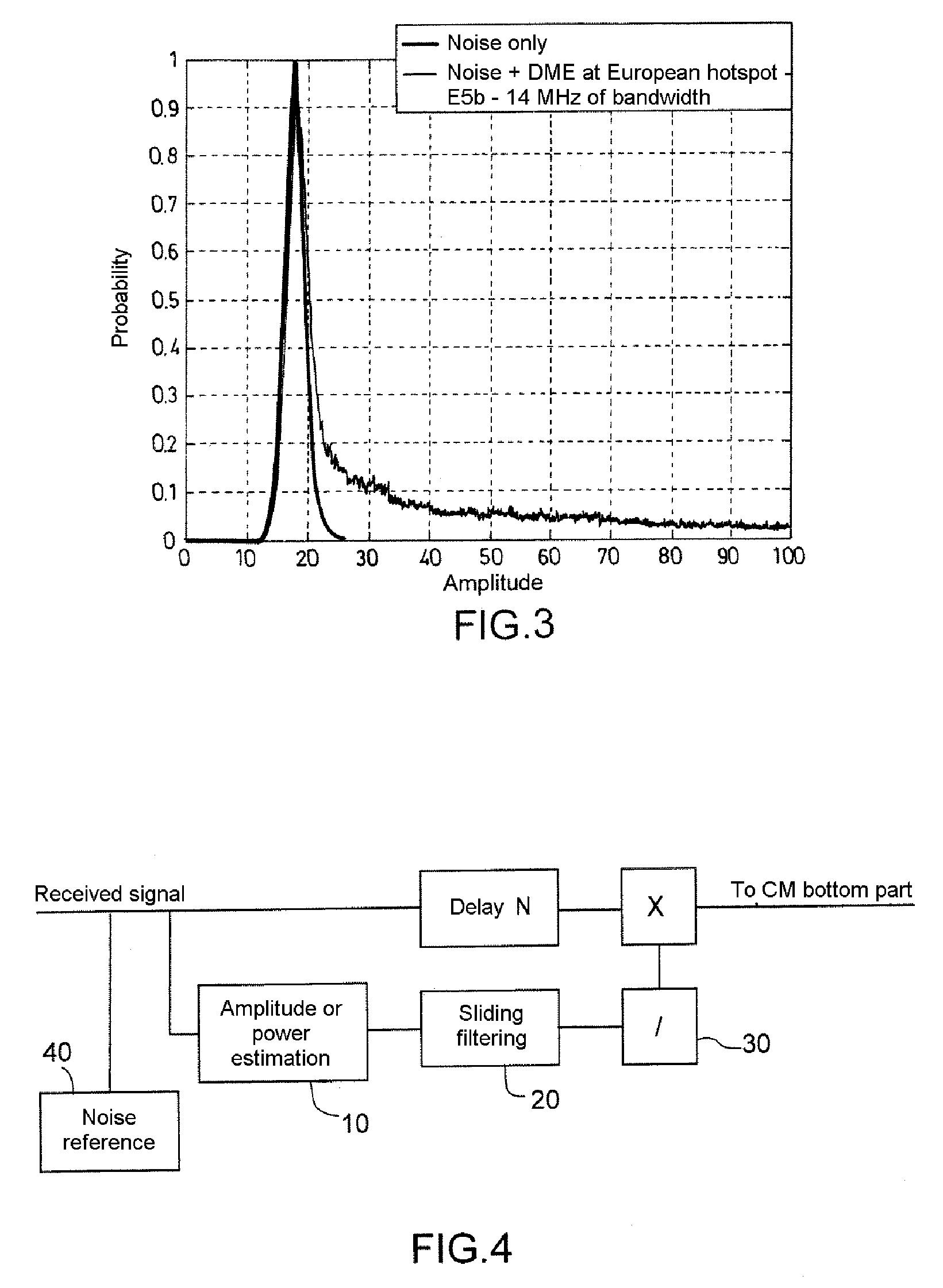
[0045]A second embodiment consists in using an unbiased estimation of the thermal noise by injection of an innovation calculated to optimize the gain of the receiver. The innovation is calculated on the basis of the analysis of the signal power or amplitude probability density function. This function is analyzed in its part where there are few high amplitude or power samples and which is affected little by the interferences as shown by FIG. 3.

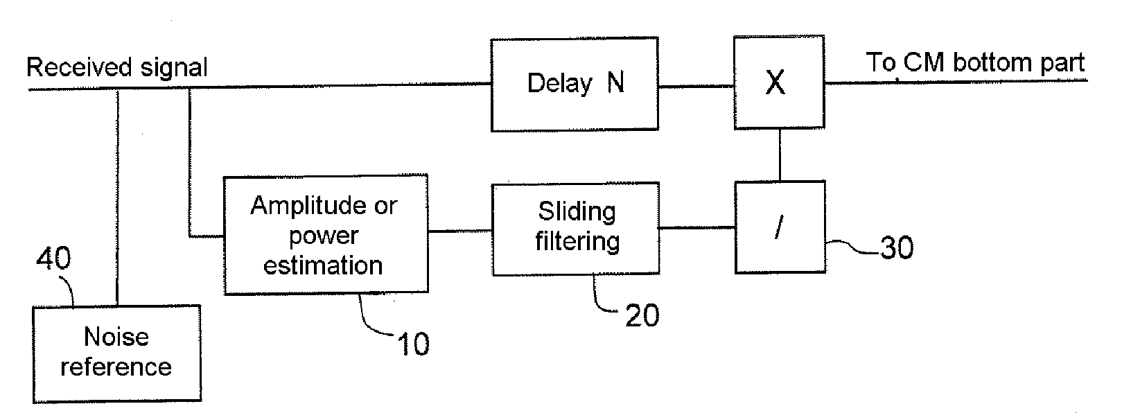
[0046]This injection can be performed synchronously. The module that is used is located in the bottom part (40) of FIG. 5. It can be located in the same FPGA as the basic device of the invention. It comprises a submodule 400 for estimating the amplitude or the power of the signal, a filtering submodule 500 which will have the same time constant as the filtering module described hereinabove. Conventionally, the device comprises an AGC submodule 60. At the input of this submodule 600, a control submodule 700, which comprises one or more non-linea...


PUM


Abstract

The invention relates to a radiofrequency receiver, notably for satellite positioning applications, needing to operate in an environment where interference is dense, notably when it involves pulses transmitted by DME beacons. Below the useful signal suppression threshold, amplitude or power are inverted to improve the dynamic interference response time. Advantageously, the useful signal suppression threshold and the set point power or amplitude are determined by analyzing the amplitude or power probability density function in its part enriched with low amplitude/power samples.

Description

RELATED APPLICATIONS[0001]The present application is based on, and claims priority from, French Application Number 07 03732, filed May 25, 2007, the disclosure of which is hereby incorporated by reference herein in its entirety.FIELD OF THE INVENTION[0002]The present invention applies to the radiofrequency receivers that have to receive weak signals in a pulsed interference environment.BACKGROUND OF THE INVENTION[0003]Positioning receivers typically received weak signals in a pulsed interference environment which use the signals received from GNSS (Global Navigation Satellite System) satellite constellations such as the GPS (Global Positioning System) or enhanced GPS systems, GLONASS (Global Orbiting Navigation Satellite System) and, in the near future, Galileo. The received signal is typically located a few tens of dB below the thermal noise of the receiver. The signal processing needs to allow for the recovery of one or more carriers and one or more modulation codes of said carrie...

Claims


Application Information

Patent Timeline
Patent Type & Authority Applications(United States)
IPC IPC(8): H04B1/00G01S19/21
CPCG01S19/21
Inventor KIRBY, ESTELLERENARD, ALAIN
Owner THALES SA
Why Eureka
Try Eureka