Dental Treatment Apparatus With Automatic Tip Recognition

a technology of automatic recognition and dental treatment, applied in dentistry, dental science, tooth cleaning, etc., can solve the problems of not enabling the type of tip mounted on the handpiece to be identified, unable to adjust the generator on a power and amplitude, and complicated use of the dental treatment appliance for the practitioner

Active Publication Date: 2008-11-27
SOC POUR LA CONCEPTION DES APPL DES TECHN ELECTRONIQUES SATELEC
View PDF19 Cites 56 Cited by
  • Summary
  • Abstract
  • Description
  • Claims
  • Application Information

AI Technical Summary

Benefits of technology

[0010]An object of the present invention is to remedy the above-mentioned drawbacks and to propose a solution that avoids any intervention on th

Problems solved by technology

Nevertheless, whatever the identification technique used, selecting the power range on the ultrasound generator requires intervention on the part of the practitioner, thereby complicating the use of the dental treatment appliance for the practitioner, and not eliminating the risk that the wrong power range might be selected on the generator.
However, although that document discloses

Method used


Image

  • Dental Treatment Apparatus With Automatic Tip Recognition
  • Dental Treatment Apparatus With Automatic Tip Recognition
  • Dental Treatment Apparatus With Automatic Tip Recognition

Examples


first embodiment

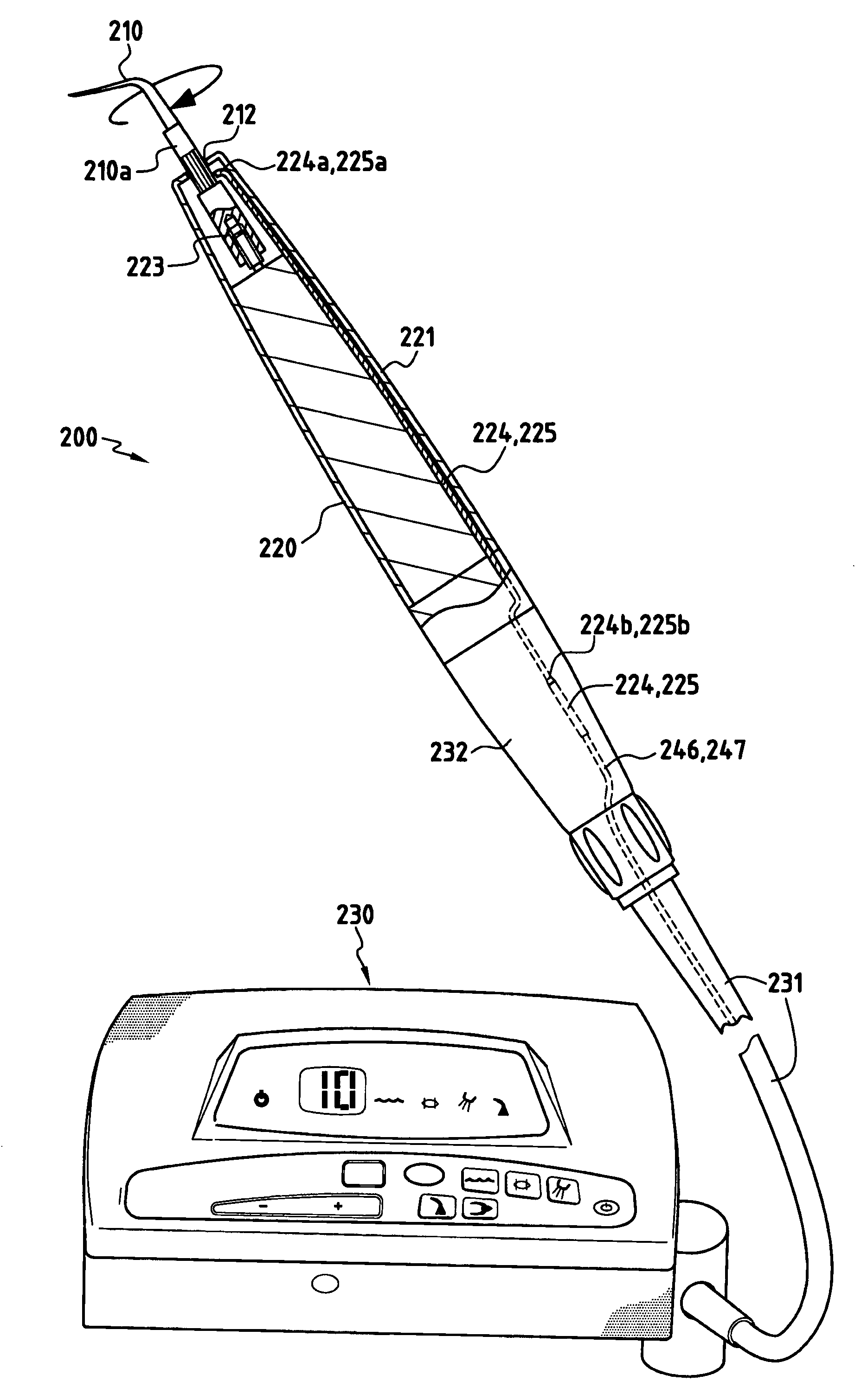
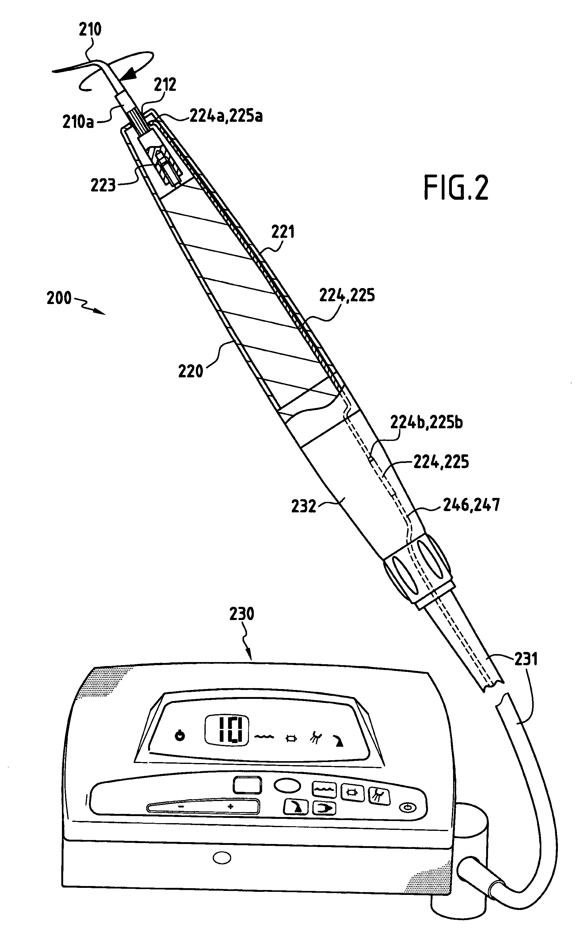
[0032]FIG. 2 shows an ultrasound dental treatment appliance 200 constituting the invention. The appliance 200 is constituted by a handpiece 220 provided with a tip 210 and connected to an ultrasound generator 230 by means of a cord 231.

[0033]The ultrasound appliance in this embodiment includes means for optically detecting the type of tip for determining the power and amplitude range in which the tip is to be used. For this purpose, and as shown in FIG. 2, the appliance uses a tip 210 that carries a bar code 212 placed around its base 210a. In conventional manner, the tip is mechanically coupled in rigid manner to the transducer (not shown) of a handpiece 220 by being screwed onto an element 223 secured to the transducer (not shown) of the handpiece 220. Two optical fibers 224 and 225 are placed side by side in the body 221 of the handpiece. The fibers 224 and 225 are molded in the body 221, for example. The respective ends 224a and 225a of the optical fibers 224 and 225 open out fr...

second embodiment

[0041]FIG. 6 shows an ultrasound treatment appliance 300 constituting the invention and constituted by a handpiece 320 provided with a tip 310 and connected to an ultrasound generator 330 by means of a cord 331.

[0042]In this embodiment, the ultrasound appliance detects the power and amplitude range in which the tip is to be used by a radio frequency (RF) technique. For this purpose, and as shown in FIG. 6, the appliance uses a tip 310 which includes in its base 310a a transponder 312. The transponder 312 can be a miniature component using RFID technology. In well-known manner, this type of component is a passive circuit including an inductance-capacitance (LC) type resonator (antenna) suitable for picking up an electromagnetic field at a given frequency in order to power the component. This electromagnetic field is generated by a solenoid antenna 324 disposed in the body 321 of the handpiece 320 (e.g. by being molded therein).

[0043]Once it is powered, the circuit responds by deliver...

third embodiment

[0045]With reference to FIG. 8 there follows a description of the ultrasound appliance which, in accordance with the invention, enables the type of tip mounted on the handpiece to be recognized automatically and enables the corresponding power range to be selected automatically for the ultrasound generator. In this embodiment, the type of tip is recognized by frequency analysis of an electronic signal supplied to the transducer 410 of the handpiece. For this purpose, a frequency wobulator 401 is used that generates a signal around the resonant frequency of the assembly constituted by the transducer and the tip mounted on the handpiece. The current i(t) and the voltage v(t) at the terminals of the transducer are measured and converted into a digital signal by an analog-to-digital converter circuit 403. The digital signal is then forwarded to a calculator circuit 405 that serves to find the resonant frequencies of the transducer (its modes), its phase, its power, and its impedance. Th...


PUM


Abstract

The invention relates to an ultrasound dental treatment appliance comprising a surgical handpiece (220) fitted with a transducer connected to an ultrasound generator (230), the handpiece being designed to receive ultrasound tips (210) that are mechanically coupled to the transducer and that operate in different ultrasound wave power and amplitude ranges. The dental treatment appliance includes means (224, 225), e.g. optical means, for automatically detecting the utilization power and amplitude range of the tip (210) mounted on the handpiece, and processor means for automatically setting the ultrasound generator to the detected power and amplitude range.

Description

BACKGROUND OF THE INVENTION[0001]The present invention relates to dental treatment appliances, and more particularly to ultrasound appliances, such as scaling appliances, surfacing appliances (for eliminating biofilms), or cutting appliances (cavities or preparations for a prosthesis), all comprising instruments that vibrate at ultrasound frequencies.[0002]FIG. 1 shows an ultrasound treatment appliance 100 that comprises an ultrasound generator 110 connected to a handpiece 120 via a cord 111. A sonotrode or ultrasound tip 130 is mounted at the end of the handpiece 120. In well-known manner, the handpiece 120 includes a transducer (not shown) e.g. made of piezoelectric material, and coupled mechanically to the tip 130 in such a manner as to transmit vibratory waves thereto at an amplitude that is determined as a function of the power delivered by the ultrasound generator 110.[0003]The tip is an interchangeable part that presents a wide variety of shapes depending on the treatment for...

Claims


Application Information

Patent Timeline
IPC IPC(8): A61C1/07
CPCA61C1/0015A61C1/07A61C3/03A61C17/20A61C2204/005
Inventor REGERE, PASCALDIERAS, FRANCIS
Owner SOC POUR LA CONCEPTION DES APPL DES TECHN ELECTRONIQUES SATELEC
Why Eureka
Try Eureka