Balloon Cannulae

a technology of balloon cannula and helical tube, which is applied in the field of new design of balloon cannula, can solve the problems of inability to provide a truly symmetrical placement of an inflated balloon around a central lumen of standard diameter, unpredictable and suboptimal flow characteristics, and increase the likelihood of intimal vascular injury and clot or plaque embolization, so as to reduce tissue trauma, minimize the chance of caval injury, and eliminate the need for circumfer

Inactive Publication Date: 2008-11-27
CARTLEDGE RICHARD +1
View PDF0 Cites 13 Cited by
  • Summary
  • Abstract
  • Description
  • Claims
  • Application Information

AI Technical Summary

Benefits of technology

[0018]The present invention is directed towards a novel design for balloon cannulae to be used when bi-caval cannulation of the heart is indicated, eliminating the need to perform circumferential caval dissection and further reducing the tissue trauma caused by prior art balloon cannulae. Balloon cannulae according to a disclosed embodiment of the present invention comprise inflatable, occlusive balloons adjacent to the cannulae's distal ends. While these cannulae are inserted and positioned by a surgeon in the standard fashion, the need for circumferential dissection of the cavae and tourniquet placement is obviated. After the cannulae are positioned and secured with purse string sutures, the surgeon inflates the occlusive balloons by infusing an inflation medium with a syringe or other means. Once the balloons are inflated, all of the venous return is diverted. The balloons inflate around the distal ends of the cannulae and allow blood to flow through the lumen of the cannulae, but not around the balloons. Use of these cannulae minimizes the chance of caval injury by eliminating the need for circumferential dissection. Additionally, the configuration of the balloon in relation to the cannula is such that the balloon is “flush” with the cannula so that no acute change in diameter exists along the external surface of the cannula, which serves to avoid tissue trauma during insertion and withdrawal into and out of bodily structures.
[0019]The present invention addresses several major problems presented by existing designs for balloon cannulae. In various embodiments according to the present invention, the lumens are configured such that a balloon cannula can be inflated without compromising either the flow within the principle lumen of the cannula or the seal between the cannula and the structure within which the cannula lies. Moreover, a disclosed example of a cannula according to the present invention is provided with a trough within the cannula body at its distal end in which the balloon member lies such that when uninflated during insertion and withdrawal, there is a smooth interface between the external cannula wall and the uninflated balloon allowing for smoother, easier, and safer insertion and withdrawal.
[0020]Moreover, existing designs for balloon cannulae are unable to provide a truly symmetrical placement of an inflated balloon around a central lumen of standard diameter. The asymmetry which results with conventional balloon inflation is sufficient to displace the lumen from the true center of the endovascular lumen in which the balloon cannula is placed, resulting in unpredictable and suboptimal flow characteristics therethrough. The altered hemodynamics of such flow with an existing balloon cannula increases the likelihood of intimal vascular injury and clot or plaque embolization. Balloon cannulae of the present invention achieve the surprising result of the flow characteristics of a non-balloon cannula by maintaining the preferred laminar flow characteristics of a circular main lumen of consistent diameter, positioned and maintained in or near the center of vascular flow by a balloon originally provided within a recessed trough in the exterior wall of the cannula, with accessory lumens contained within an externally circular cannular wall, allowing for better seal, less vascular trauma, and easier vascular ingress and egress.
[0021]In addition, balloon cannulae according to the present invention may be provided with stabilizing elements to anchor the inflated balloon within a vessel lumen during use. Such stabilizing elements further make use of the trough within the cannula body, with the stabilizing elements retracting into said trough during insertion and removal, allowing for smooth and trauma-free entry and egress of the cannula.
[0022]Furthermore, balloon cannulae according to the present invention may be provided with a filtration mechanism to collect and prevent embolization of plaques or thrombi that may be caused or displaced by the arteriotomy, venotomy, or cannulation of an artery or vein for placement of the balloon cannulae.

Problems solved by technology

Moreover, existing designs for balloon cannulae are unable to provide a truly symmetrical placement of an inflated balloon around a central lumen of standard diameter.
The asymmetry which results with conventional balloon inflation is sufficient to displace the lumen from the true center of the endovascular lumen in which the balloon cannula is placed, resulting in unpredictable and suboptimal flow characteristics therethrough.
The altered hemodynamics of such flow with an existing balloon cannula increases the likelihood of intimal vascular injury and clot or plaque embolization.

Method used


Image

  • Balloon Cannulae
  • Balloon Cannulae
  • Balloon Cannulae

Examples


Embodiment Construction

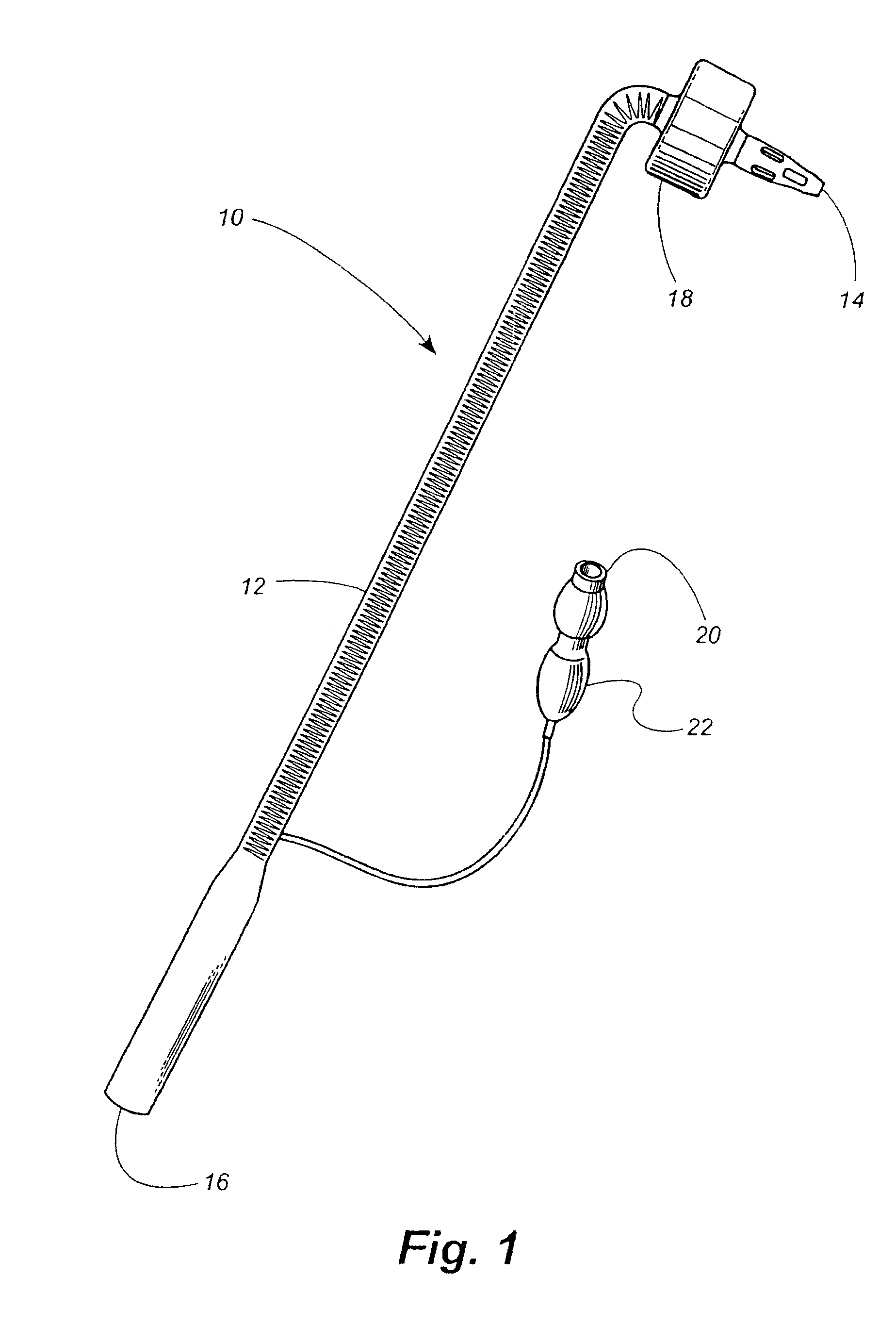
[0064]Referring now in more detail to the drawings, in which like numerals indicate like elements throughout the several views, FIG. 1 illustrates a balloon cannula 10 according to a disclosed embodiment of the present invention. The balloon cannula 10 includes an elongated, tubular cannula shaft 12 having a distal end 14 and a proximal end 16. In the disclosed embodiment, the cannula body 12 is constructed of a pliable material such as, but not limited to, natural or synthetic rubbers, elastomers, polyisoprenes, polyurethanes, vinyl plastisols, acrylic polyesters, polyvinylpyrrolidone-polyurethane interpolymers, butadiene rubbers, styrene-butadiene rubbers, rubber lattices, and other polymers or materials with similar resilience and pliability qualities. An inflatable member or balloon 18 is located adjacent the distal end 14 of the cannula shaft 12. An inflation valve 20 adapted to accommodate a syringe or other suitable apparatus branches off from the cannula shaft 12 at a locati...


PUM


Abstract

A vascular catheter with a circular external diameter, a circular lumen contained within, and an inflatable balloon that overlies a trough in the catheter body such that when the balloon is deflated, the balloon does not protrude beyond the outer circumference of the catheter shaft. The wall of the catheter shaft is thicker along one side than along the remainder of the circumference of the catheter shaft to permit an inflation lumen to be disposed within the thick wall section without increasing the outer diameter of the remaining portion of the circumference. The inflatable balloon is further disposed to maintain the circular lumen of the catheter in the center of flow of the blood vessel in which it is used, maintaining optimal flow. The combination of the circular lumen, circular outer diameter, and recessed balloon trough produces improved hemodynamic flow characteristics within the cannula over existing balloon cannula designs, minimizing flow-related injuries that might cause embolization or vascular dissection.

Description

CROSS-REFERENCE TO RELATED APPLICATIONS[0001]This application claims priority as a continuation-in-part under 35 U.S.C. §120 to U.S. patent application Ser. No. 10 / 294,336 entitled “Balloon Cannulae” and filed Nov. 2, 2002, and to U.S. Provisional Patent Application No. 60 / 344,942 entitled “Balloon Cannulae” and filed Dec. 21, 2001. The entire contents of these applications are hereby expressly incorporated by reference.FIELD OF THE INVENTION[0002]The present invention relates to the fields of cardiovascular and open heart surgery. Specifically, the present invention relates to a novel design for balloon cannulae and to methods of use for such cannulae in surgical procedures involving cardiopulmonary bypass or other high pressure infusion pumps.BACKGROUND OF THE INVENTION[0003]The cardiopulmonary bypass machine is one of the most important devices in the field of cardiac surgery. It has enabled cardiac surgeons to safely perform operations for virtually the entire spectrum of acquir...

Claims


Application Information

Patent Timeline
Patent Type & Authority Applications(United States)
IPC IPC(8): A61M25/10A61F2/958
CPCA61M25/10A61M1/3659A61M1/3666
Inventor CARTLEDGE, RICHARDLEE, LEONARD Y.
Owner CARTLEDGE RICHARD
Why Eureka
Try Eureka