Reaming device

a reaming device and a technology for bone reaming, applied in the field of bone reaming devices, can solve the problems of lack of reaming devices with the capability of tracking particular forms of cavities to be formed, and achieve the effect of reducing the cavity dimension

Inactive Publication Date: 2008-11-27
STRYKER EURO OPERATIONS HLDG LLC
View PDF33 Cites 59 Cited by
  • Summary
  • Abstract
  • Description
  • Claims
  • Application Information

AI Technical Summary

Benefits of technology

[0007]It may be seen as one aspect of the present invention to provide a reaming device being capable of tracking a particular form o...

Problems solved by technology

However, presently known solutions for a reaming device lack of a capability of tracking particula...

Method used


Image

  • Reaming device
  • Reaming device
  • Reaming device

Examples


Embodiment Construction

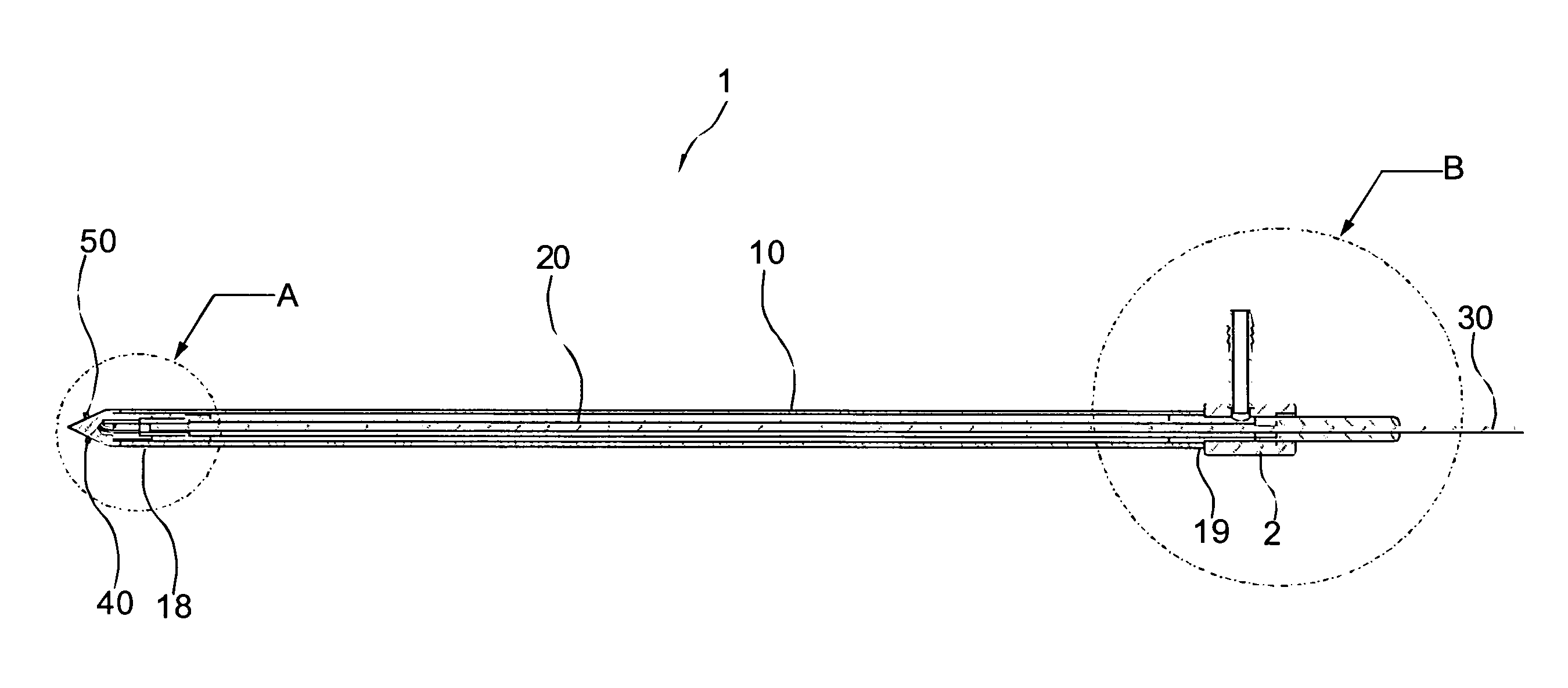
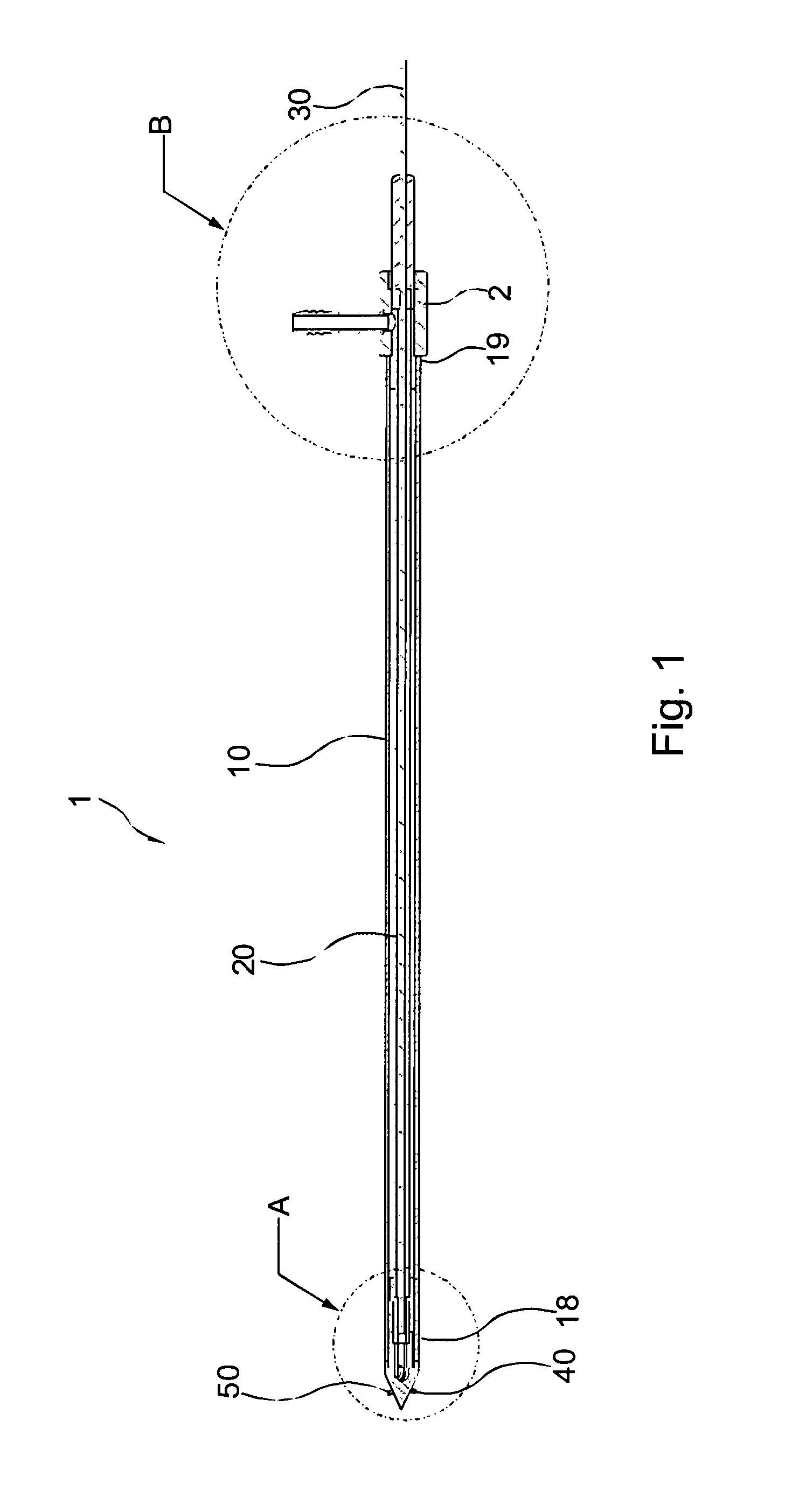
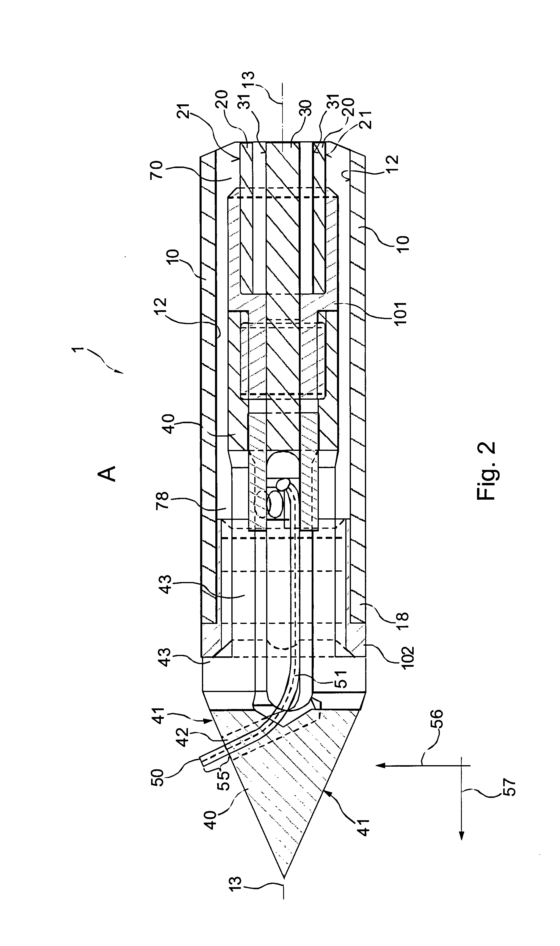
[0041]FIG. 1 illustrates a total view of the reaming device according to an exemplary embodiment of the invention. The reaming device has a head portion denoted with A, an operator portion denoted with B and a shaft portion between the head portion and the operator portion. The head portion will be inserted through an orifice or channel of the human body in order to remove or ablate tissue by means of ablation devices 50. The operator portion denoted with B remains outside the human body in order to allow the operator to handle the reaming device. For example, it is possible to remove the ablated tissue by sucking on a suction adapter or a suction device 2, when an operator handles the reaming device, in particular the shaft 30 for modifying the geometry of the protruding amount of an ablation device, which protrudes beyond an outer surface of a head portion 40. The head 40 portion is mounted on to a first shaft 10, in particular, the head is pivoted with respect to the first shaft ...


PUM


Abstract

A bone reamer has an ablation device for forming cavities in body tissue, the ablation device is movable with respect to a head of the reamer, and is capable of protruding at least partially beyond a surface of the head. The amount of protrusion the ablation device protrudes beyond the surface of the head has a variable geometry and the geometry is remotely modifiable. More particularly, the amount the ablation device extends beyond the outer surface of a reamer head body can be varied by an actuator located on the reamer outside the body.

Description

BACKGROUND OF THE INVENTION[0001]The present invention relates to a bone reaming device, and in particular to a bone reaming device having an ablation device with a variable geometry, which geometry is remotely modifiable.[0002]Surgeons are using minimally invasive surgical techniques on an increasing basis for the treatment of a wide variety of medical conditions. Such techniques typically involve the insertion of a surgical device through a natural body orifice or through a relatively small incision using a tube or cannula. In contrast, conventional surgical techniques typically involve a significantly larger incision and are therefore sometimes referred to as open surgery. Thus, as compared with conventional techniques, minimally invasive surgical techniques offer the advantages of minimizing trauma to healthy tissue, minimizing blood loss, reducing the risk of complications such as infection, and reducing recovery time. Further, certain minimally invasive surgical techniques can...

Claims


Application Information

Patent Timeline
IPC IPC(8): A61B17/58
CPCA61B17/1617A61B18/1477A61B2018/1425A61B2018/144A61B2217/005
Inventor WIELAND, MANFRED
Owner STRYKER EURO OPERATIONS HLDG LLC
Why Eureka
Try Eureka