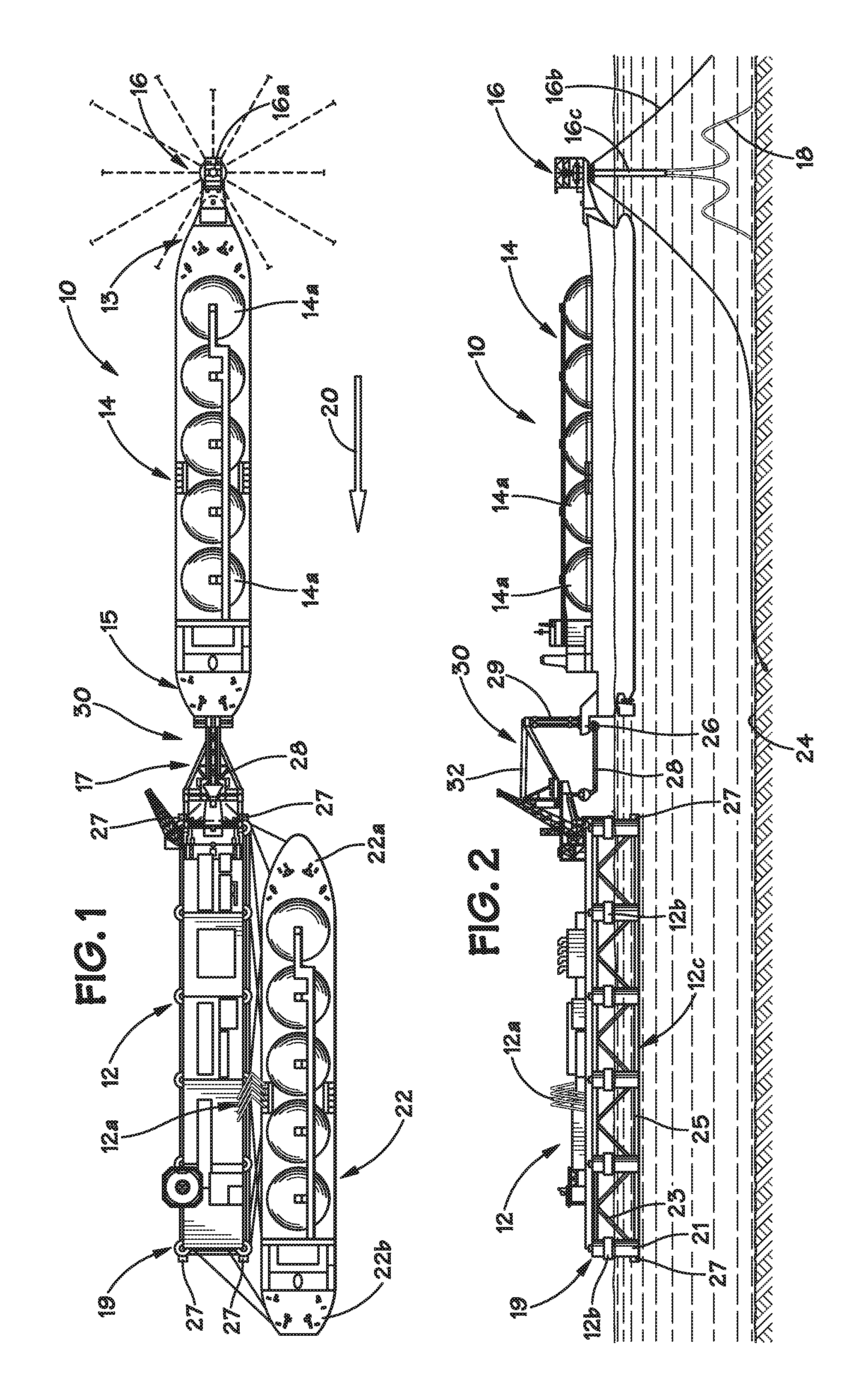
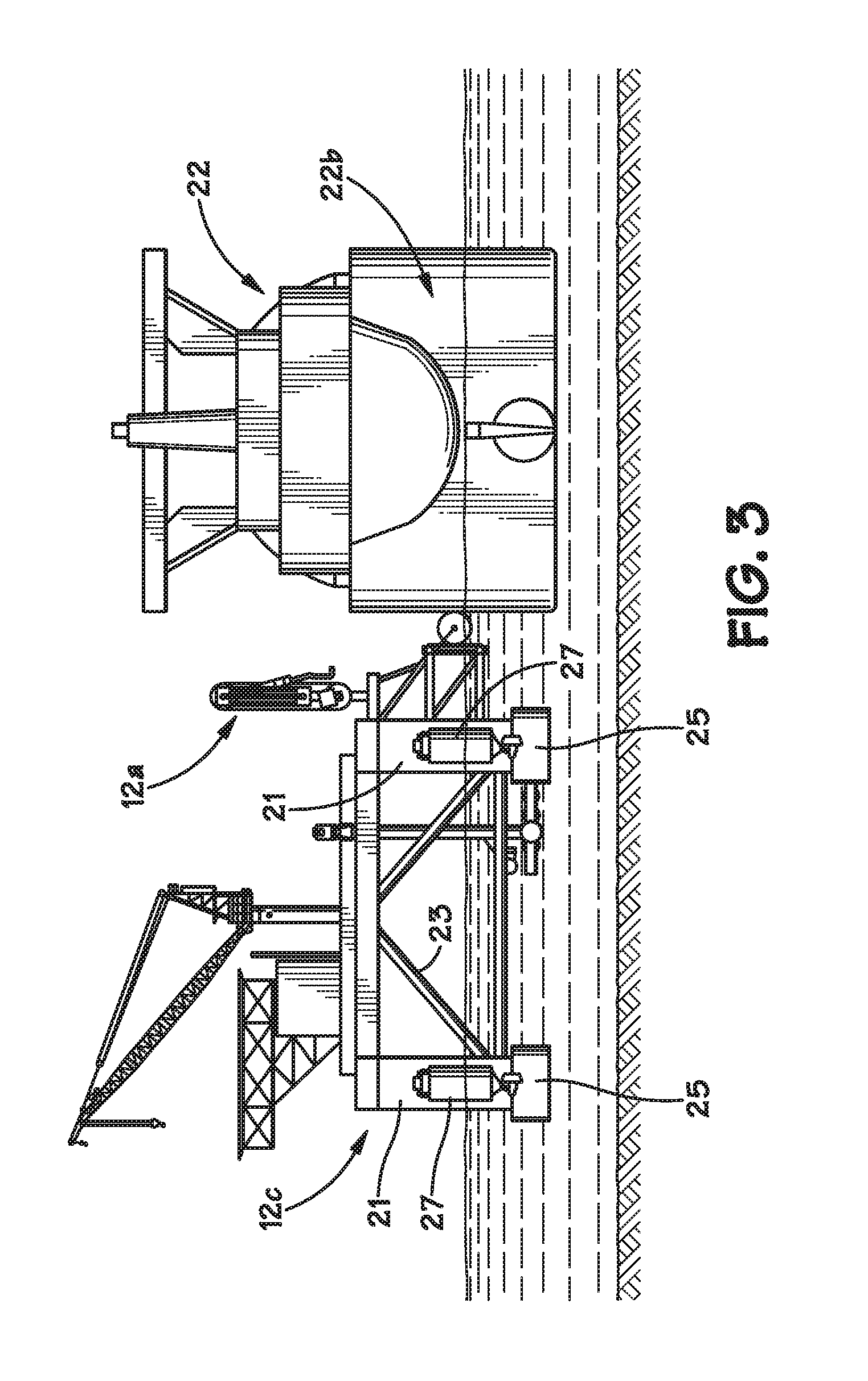
Floating LNG regasification facility with LNG storage vessel

a floating lng and storage vessel technology, applied in vessel construction, special purpose vessels, container discharging methods, etc., can solve the problems of high risk, sea-going tug boats cannot safely operate to push against the side of an lng carrier under high sea conditions, and difficulty in berthing

Inactive Publication Date: 2008-12-04
SOFEC
View PDF19 Cites 41 Cited by
  • Summary
  • Abstract
  • Description
  • Claims
  • Application Information

AI Technical Summary

Benefits of technology

[0008]The following presents a simplified summary of the invention in order to provide a basic understanding of some aspects of the invention. This summary is not an exhaustive overview of the invention. It is not intended to identify key or critical elements of the invention or to delineate the scope of the invention. Its sole purpose is to present some concepts in a simplified form as a prelude to the more detailed description that is discussed later.

Problems solved by technology

The marine operations involved in safely berthing an LNG carrier to another floating vessel in the open sea are known by the offshore industry to be a dangerous, high risk endeavor.
It is generally understood that sea-going tug boats cannot safely operate to push against the side of an LNG carrier under high sea conditions, e.g., seas having a significant wave height (Hs) greater than about 1-1.5 meters.
To the extent that the LNG carrier and the other floating vessel to which it will be berthed have traditional hull configurations, the problems associated with berthing may be more difficult as both vessels may tend to roll with an increasing relative magnitude as they approach one another.
In many situations, the regasification process is a limiting factor as it relates to how fast the LNG can be offloaded from an LNG carrier vessel.
The specialized LNG carrier vessels are very expensive to operate.
The time spent in completely offloading a loaded LNG carrier vessel is very expensive.
Moreover, the longer the loaded LNG carrier vessel remains positioned beside the regasification vessel and connected for offloading LNG, the greater the possibility of mishaps or accidents occurring.
With existing offshore LNG terminals, depending upon the timing of the customer's overall product demand and the arrival of the seagoing LNG carrier vessels, it may not be possible to supply the purchased product in a continuous fashion.

Method used


Image

  • Floating LNG regasification facility with LNG storage vessel
  • Floating LNG regasification facility with LNG storage vessel
  • Floating LNG regasification facility with LNG storage vessel

Examples


Embodiment Construction

[0020]Illustrative embodiments of the invention are described below. In the interest of clarity, not all features of an actual implementation are described in this specification. It will of course be appreciated that in the development of any such actual embodiment, numerous implementation-specific decisions must be made to achieve the developers' specific goals, such as compliance with system-related and business-related constraints, which will vary from one implementation to another. Moreover, it will be appreciated that such a development effort might be complex and time-consuming, but would nevertheless be a routine undertaking for those of ordinary skill in the art having the benefit of this disclosure.

[0021]The present invention will now be described with reference to the attached figures. The words and phrases used herein should be understood and interpreted to have a meaning consistent with the understanding of those words and phrases by those skilled in the relevant art. No...


PUM


Abstract

An LNG terminal is disclosed which includes an offshore mooring turret, an LNG storage vessel operatively coupled to the mooring turret, the LNG storage vessel including at least one LNG storage tank for the storage of liquid natural gas and a regasification vessel operatively coupled to the LNG storage vessel. A method of operating an offshore LNG terminal is also disclosed which includes obtaining liquefied natural gas from at least one LNG storage tank on an LNG storage vessel that is operatively coupled to a mooring turret, regasifying the liquefied natural gas from the LNG storage vessel using a regasification vessel operatively coupled to the LNG storage vessel, and supplying the regasified gas to at least one subsea pipeline via the mooring turret.

Description

BACKGROUND OF THE INVENTION[0001]1. Field of the Invention[0002]The present invention is generally related to liquid natural gas (LNG) processing systems, and, more particularly, to a floating LNG regasification facility with an LNG storage vessel.[0003]2. Description of the Related Art[0004]Natural gas is captured from subterranean structures via natural gas wells. The natural gas is then processed to convert it from a gaseous state to a liquid state—liquefied natural gas (LNG). LNG is typically transported as a liquid via specialized LNG carrier vessels. A floating LNG terminal is provided for offloading the LNG carrier vessel in the sea. The floating LNG terminal typically comprises a regasification vessel that is used to regasify the LNG, i.e., to convert the liquid gas to its gaseous form. The gas is then transported to various onshore facilities via undersea gas pipelines.[0005]The marine operations involved in safely berthing an LNG carrier to another floating vessel in the o...

Claims


Application Information

Patent Timeline
Patent Type & Authority Applications(United States)
IPC IPC(8): F17C9/02B63B21/00
CPCB63B21/50B63B35/44F17C7/04F17C2265/05F17C2201/0128F17C2201/052F17C2205/0184F17C2221/033F17C2223/0161F17C2223/033F17C2225/0123F17C2225/036F17C2227/0135F17C2227/0302F17C2270/0105F17C2270/0113F17C2270/0121B63B25/16B63B27/34
Inventor BOATMAN, L. TERRYLIU, YONGHUI
Owner SOFEC
Why Eureka
Try Eureka