Powershift Transmission Clutch System With A Predetermined Running Clearance

a transmission clutch and predetermined technology, applied in the direction of fluid actuated clutches, clutches, non-mechanical actuated clutches, etc., can solve the problems of clutch disks slipping with respect to each other, and achieve the effects of improving operator comfort, reducing windage loss, and improving transmission shift quality

Inactive Publication Date: 2008-12-04
DEERE & CO
View PDF10 Cites 15 Cited by
  • Summary
  • Abstract
  • Description
  • Claims
  • Application Information

AI Technical Summary

Benefits of technology

[0010]The present invention provides a simplified and improved clutch piston retractor system for controlling the running clearance of clutch plate(s) to minimize windage loss and to improve transmission shift quality. This improved shift quality is desirable to improve operator's comfort, reduce shock loads on power transmission components, and to reduce the energy input to the clutches when changing gears during the acceleration and deceleration of the vehicle. Usually, high loads on the clutches can result in the clutch disks slipping with respect to each other, even when the clutch is engaged. The clutch piston retractor system solves this problem by self adjusting itself to accommodate for the wear to the disks and optimizing the shift quality, while compensating for the additional travel distance. Thus, the need to periodically recalibrate the entire system is eliminated.

Problems solved by technology

Usually, high loads on the clutches can result in the clutch disks slipping with respect to each other, even when the clutch is engaged.

Method used


Image

  • Powershift Transmission Clutch System With A Predetermined Running Clearance
  • Powershift Transmission Clutch System With A Predetermined Running Clearance
  • Powershift Transmission Clutch System With A Predetermined Running Clearance

Examples


Embodiment Construction

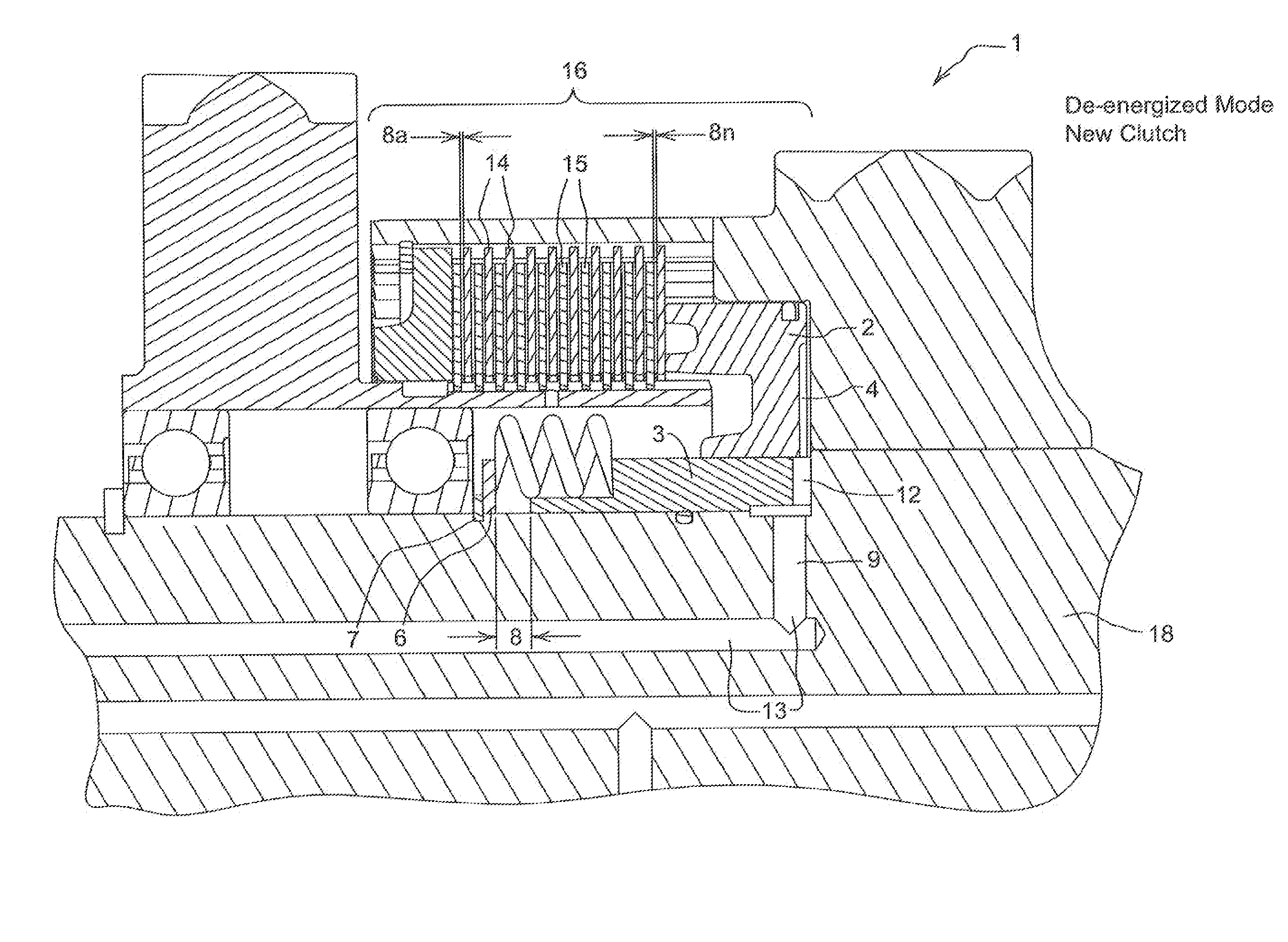
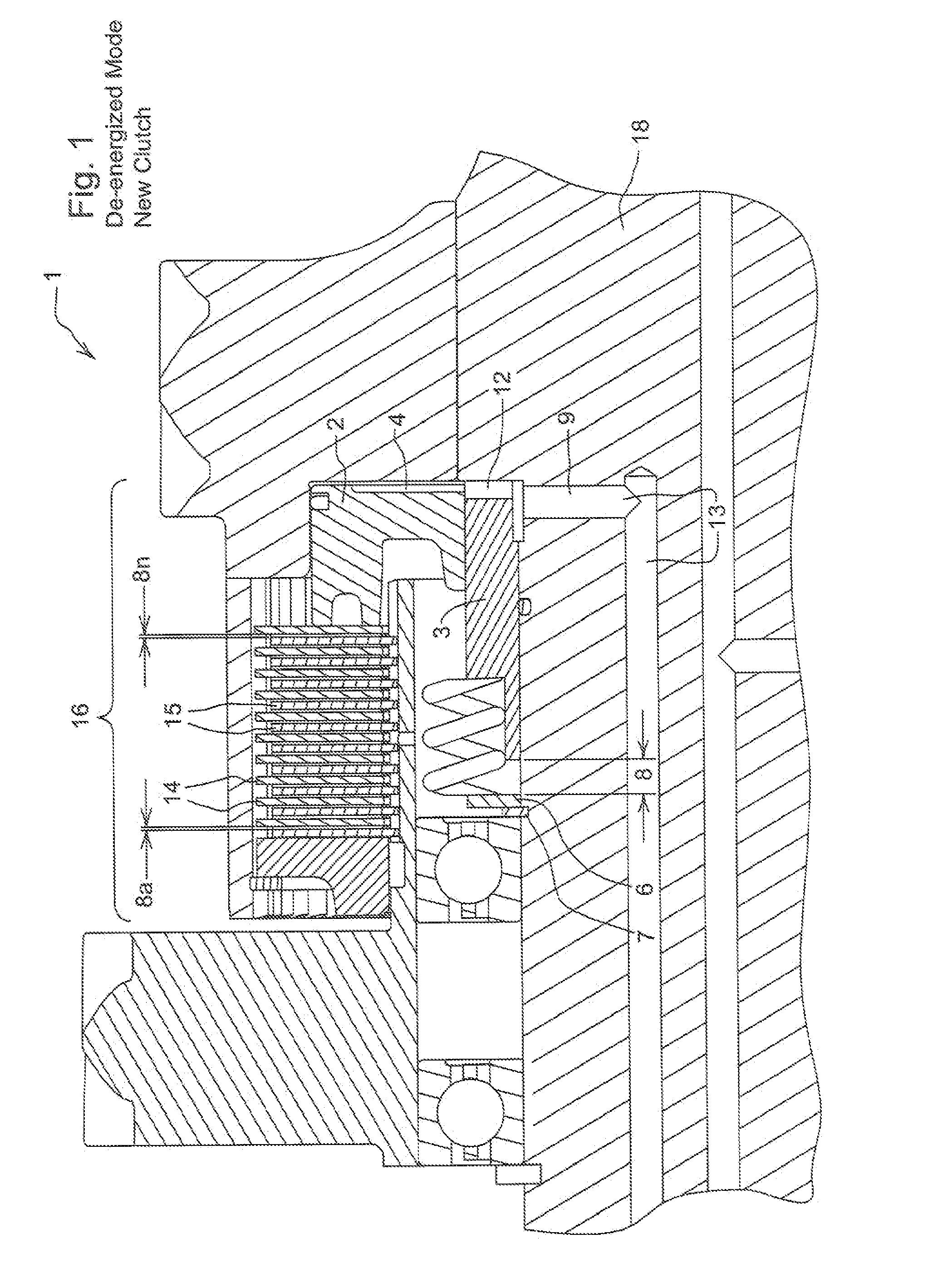
[0017]Reference is made first to FIG. 1, which shows an embodiment of the invention using a simple clutch piston retractor system comprised of a hydraulic clutch piston 2, and a sleeve 3 which is press-fitted onto the bore of the hydraulic clutch piston 2, to automatically adjust and position the sleeve 3 to control the clutch running clearance 8 to a pre-determined amount, regardless of how much wear clutch separator plates 14 and friction plates 15 have accumulated.

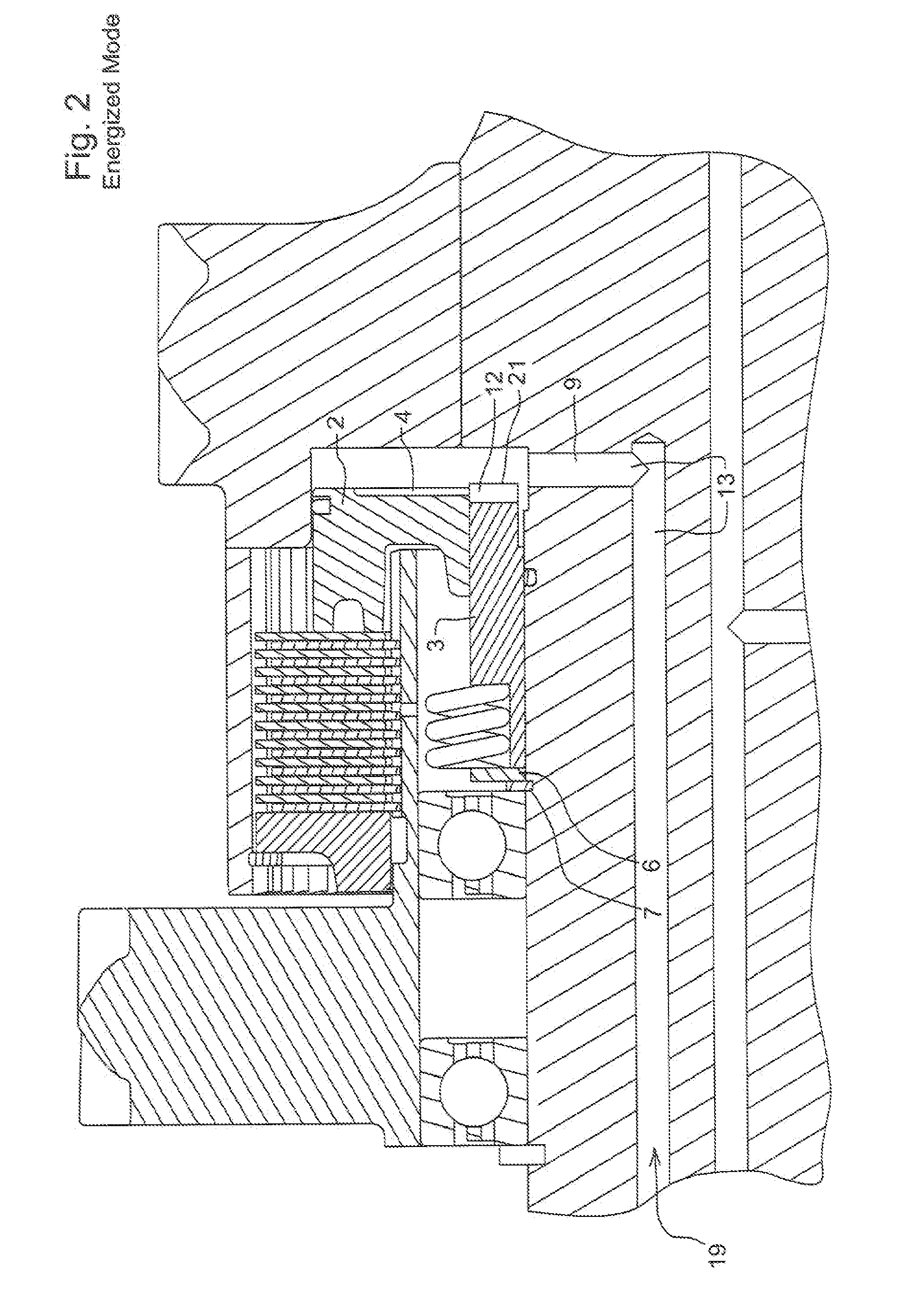
[0018]Within the clutch housing 16 is a sleeve 3 that is press fitted onto the bore of the hydraulic clutch piston 2 and both are configured to move together during normal operation, and slip relative to each other to make adjustment for maintaining optimized total running clearance 8. Where total running clearance 8 is the sum of individual running clearance 8a through 8n between separator plates 14 and friction plates 15. When clutch 1 is energized, FIG. 2, the pressurized hydraulic fluid 13 or clutch lube pressure 13...


PUM


Abstract

A simplified and improved clutch piston, retractor system is provided for controlling the running clearance of clutch plate(s) to minimize windage loss and to improve transmission shift quality. This improved shift quality helps improve operator's comfort reduce shock loads on power transmission components, and reduce the energy input to the clutches when changing gears during the acceleration and deceleration of the vehicle. The clutch piston retractor system is self adjusting to accommodate wear to the clutch disks and optimize the shift quality, while compensating for the additional travel distance. Thus, the need to periodically recalibrate the entire system is eliminated.

Description

FIELD OF THE INVENTION[0001]The present invention relates generally to a transmission clutch system in a moving vehicle, and more importantly to an apparatus for maintaining the optimized running clearance of the clutch plate(s) to minimize windage loss, and to improve transmission shift quality.BACKGROUND OF THE INVENTION[0002]Powershift transmission clutches are commonly used in a variety of work vehicles. Powershift transmission clutches generally include a clutch drum (driving or driven member) having an expandable piston operating fluid chamber or piston cavity, a piston axially slidably positioned against the piston-operating piston cavity, a clutch hub (driven member) coaxially disposed in the clutch drum, and a clutch plate pack interposed between the clutch drum and the clutch hub having one end directed to die piston. The clutch plate pack includes first and second groups of plates which are alternately juxtaposed. When the piston cavity is fed with pressurized operating f...

Claims


Application Information

Patent Timeline
Patent Type & Authority Applications(United States)
IPC IPC(8): F16D25/06
CPCF16D25/0638F16D25/126
Inventor VU, THOMAS HUNGELKE, CRAIG R.GRAY, JOE R.
Owner DEERE & CO
Why Eureka
Try Eureka