Washing machine apparatus and method

a technology for washing machines and brakes, applied in the direction of motor/generator/converter stoppers, dynamo-electric converter control, sustainable buildings, etc., can solve the problems of affecting the life of the washing machine, affecting the wear and tear of the brakes, and the use of brake pads or shoes to stop the washing machine tub is costly

Inactive Publication Date: 2008-12-04
GENERAL ELECTRIC CO
View PDF31 Cites 37 Cited by
  • Summary
  • Abstract
  • Description
  • Claims
  • Application Information

AI Technical Summary

Benefits of technology

[0014]A washing machine is provided that includes an induction motor and a motor control circuit with a feedback loop. The feedback loop provides rotor speed to a microprocessor of the motor control circuit. The motor control circuit and feedback loop control the motor such that the motor operates in a negative slip mode which provides braking to the washing machine.

Problems solved by technology

The use of brake pads or shoes to stop a washing machine tub is costly and also affects the life of the washing machine dependent upon use since each brake shoes or pad has a wear surface that is subject to wear and eventually, after a period of use, will fail due to wear.
A large load may spin longer and at greater angular velocity than a small load; thus causing greater wear on the brake.
A higher water level, using more water than a lower level, less full load, would also require additional spin for water removal and could cause greater wear on the brake.

Method used


Image

  • Washing machine apparatus and method
  • Washing machine apparatus and method
  • Washing machine apparatus and method

Examples


Embodiment Construction

Washing Machine Introduction

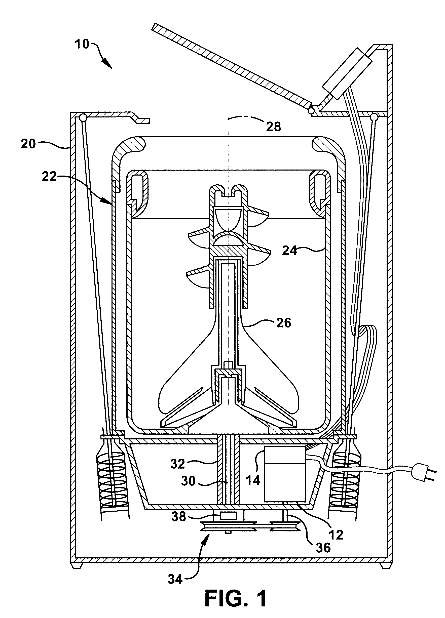
[0029]Referring to the drawings and in particular to FIG. 1, a washing machine (“washer”) according to an exemplary embodiment of the present invention is illustrated and is generally referred to by reference numeral 10. For purposes of clarity, only those aspects of washer 10 necessary for understanding of the present disclosure are described herein.

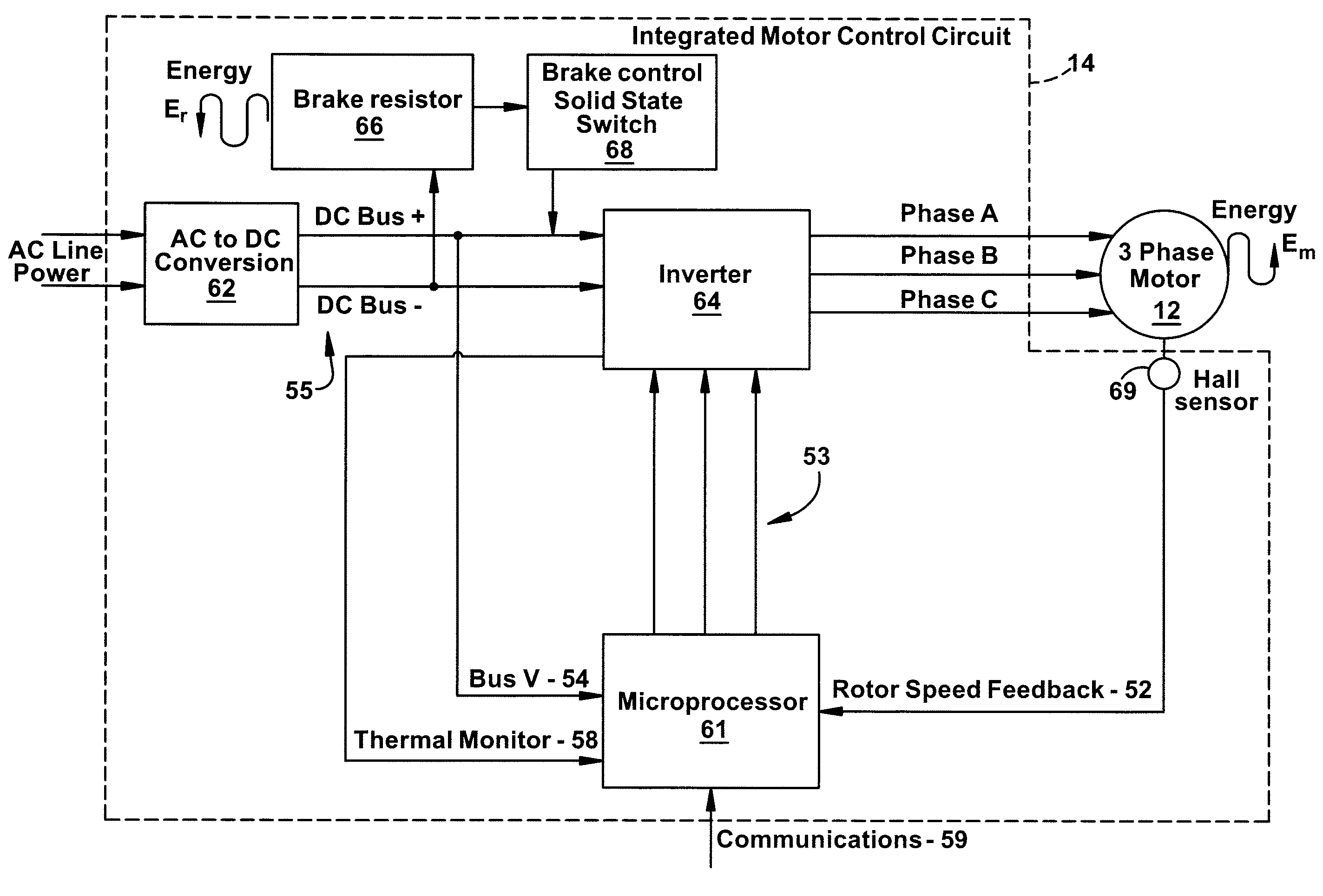
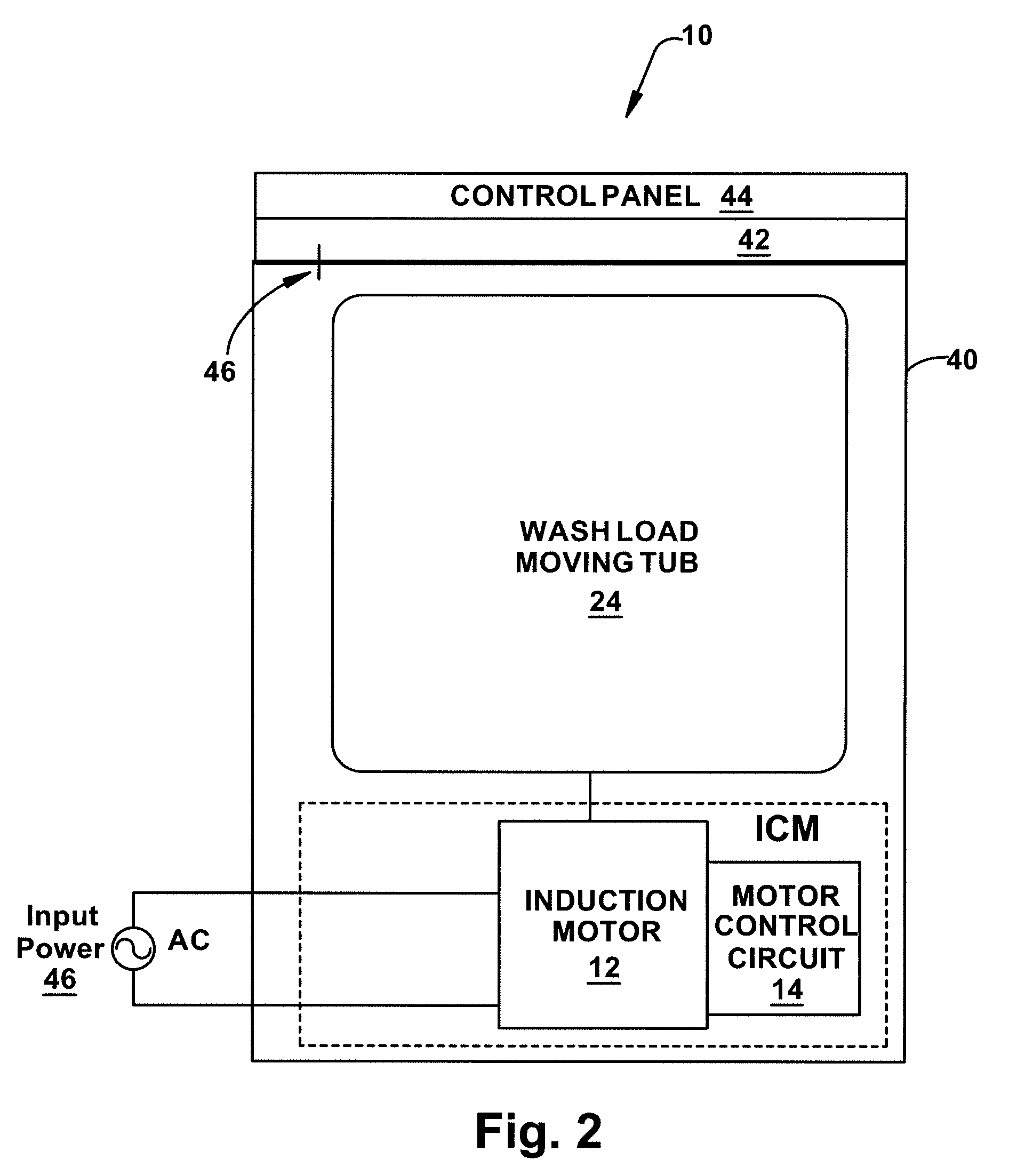
[0030]Washer 10 includes a motor 12 and a motor control unit 14. Motor 12 is three-phase alternating current (AC) induction motor and, in some embodiments includes motor control unit 14 integral therewith. The motor control, integral therewith is referred to herein as integrated motor control (ICM) or control circuitry. Motor control unit 14 can include circuitry customized for an exemplary embodiment of the present invention.

[0031]Washer 10 includes an outer housing 20 supporting a fixed tub 22, a basket or moving tub (“tub”) 24, an agitator 26, motor 12, and motor control unit 14 in a known manner. Agitator...


PUM


Abstract

A washing machine is provided that includes an induction motor and a motor control circuit with a feedback loop. The feedback loop provides rotor speed to a microprocessor of the motor control circuit. The motor control circuit and feedback loop control the motor such that the motor operates in a negative slip mode which provides braking to the washing machine.

Description

BACKGROUND OF THE INVENTION[0001]1. Field of the Invention[0002]The present disclosure is related to washing machines. More particularly, the present disclosure is related to washing machine braking.[0003]2. Description of Related Art[0004]Vertical axis washing machines, also known as top loading washing machines, represent a large portion of the overall washing machine consumer market in the United States. Horizontal axis washing machines represent a smaller segment of the United State market and abroad typically represent a larger portion of the overall washing machine consumer market.[0005]Most vertical axis washing machines include a spin cycle for removing water and / or detergents from the laundry using centrifugal force and spinning a wash load tub, also referred to as a laundry tub (“tub”) or basket. During a typical spin cycle, the motor, typically an induction motor, of the washing machine spins the tub at relatively high speed(s).[0006]Historically induction motors used in ...

Claims


Application Information

Patent Timeline
Patent Type & Authority Applications(United States)
IPC IPC(8): H02P3/18D06F33/02
CPCD06F37/304D06F2202/065D06F2204/065Y02B40/52Y02B40/00D06F2103/24D06F34/08D06F2105/48D06F2103/46
Inventor HOLLENBECK, ROBERT KEITHBRUBAKER, JUSTINCROWELL, JAMES ROBERTLEY, BRUCE CALVIN
Owner GENERAL ELECTRIC CO
Why Eureka
Try Eureka