
Adjustable over current protection circuit with low power loss

Inactive Publication Date: 2008-12-04
LEADTREND TECH
View PDF2 Cites 111 Cited by
  • Summary
  • Abstract
  • Description
  • Claims
  • Application Information

AI Technical Summary

Benefits of technology

[0009]Therefore, one objective of the present invention is to provide an adjustable over-current protection circuit able to compensate for the above-mentioned delay problems while exhibiting low power consumption.

Problems solved by technology

In practice, however, the over-current protection circuit cannot act instantly when it detects an over-current situation: there is a delay (0.1-0.3 μs) inherent in circuit from the time the over-current protection circuit is triggered to the time it outputs a control signal to turn off the power switching transistor.
Then the damage caused from the imprecise over-current protection mechanism becomes more severe.
Another reason resulting in the imprecise over-current protection mechanism is that the resistor-capacitor circuit, utilized to filter out the turn-on spike of the transistor in the voltage converter, delays the shutdown time of the transistor.
Hence, it takes longer for the overage current to be stopped after the over-current protection circuit has detected the over-current situation, causing even greater possibility of damage to the voltage converter due to poor response time.
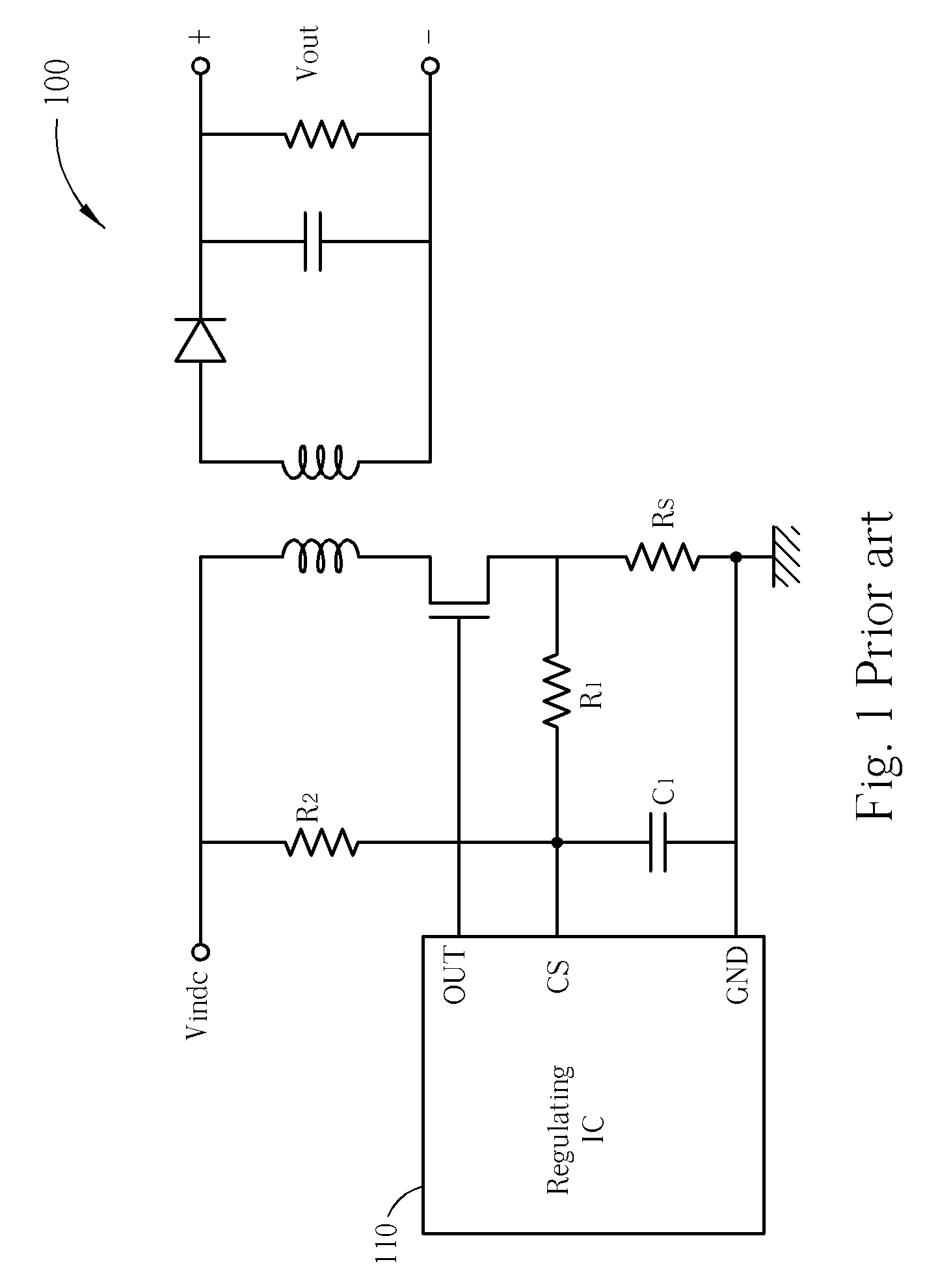
Although the addition of R2 solves the problem it increases the power loss consumed by the voltage converter 100.
Therefore, the voltage converter 100 may not conform to power saving requirements.
Increasing the resistance R1, however, will make the resistive-capacitive (RC) time constant larger and worsen the delay resulting from the resistor-capacitor circuit mentioned above.
In addition, increasing the resistance R2 will increase the noise of the circuit, influencing the detection of the regulating IC 110.
That is, the power loss problem existing in the conventional voltage converter 100 cannot be properly overcome.

Method used


Image

  • Adjustable over current protection circuit with low power loss
  • Adjustable over current protection circuit with low power loss
  • Adjustable over current protection circuit with low power loss

Examples


Embodiment Construction

[0020]Certain terms are used throughout the description and following claims to refer to particular components. As one skilled in the art will appreciate, manufacturers may refer to a component by different names. This document does not intend to distinguish between components that differ in name but not function. In the following description and in the claims, the terms “include” and “comprise” are used in an open-ended fashion, and thus should be interpreted to mean “include, but not limited to . . . ”. Also, the term “couple” is intended to mean either an indirect or direct electrical connection. Accordingly, if one device is coupled to another device, that connection may be through a direct electrical connection, or through an indirect electrical connection via other devices and connections.

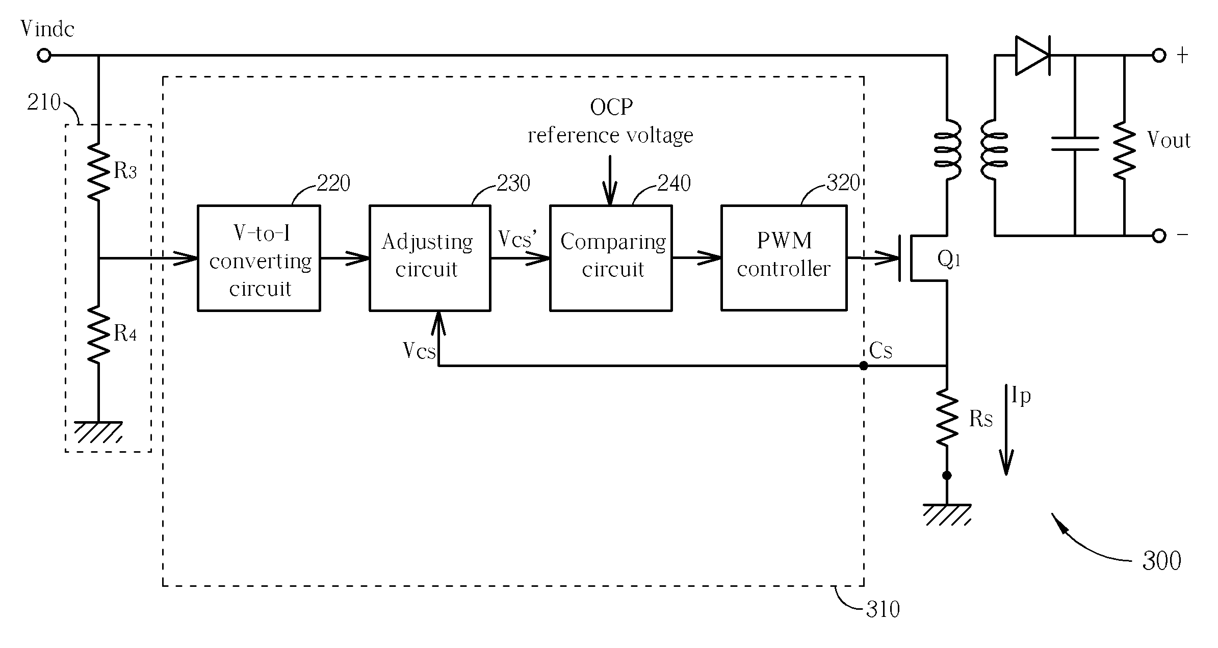
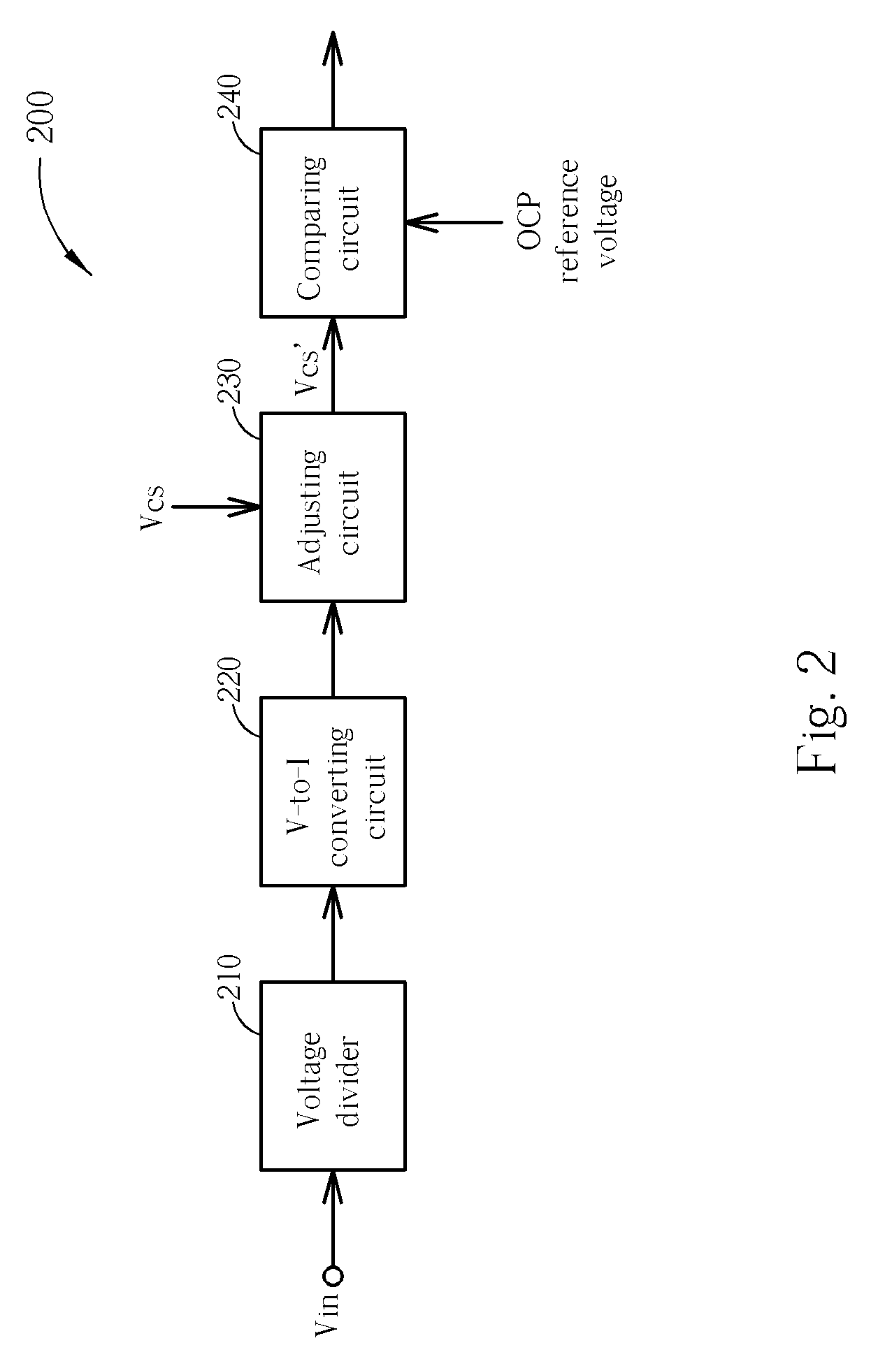
[0021]Please refer to FIG. 2, which is a diagram of an over-current protection circuit according to an exemplary embodiment of the present invention. The over-current protection circuit 200 c...


PUM


Abstract

Disclosed is an adjustable over current protection circuit which advances the timing of enabling an over current protection mechanism according to an input voltage, therefore the delay problem resulting from the non-instant response of the over current protection circuit is compensated with a low power loss. The over current protection circuit includes a voltage divider, a voltage-to-current converting circuit, an adjusting circuit and a comparing circuit. The voltage divider divides an input voltage to generate an adjusted input voltage, and the adjusted input voltage is converted into an adjusted input current by the voltage-to-current converting circuit. The adjusting circuit then adjusts a current sensing voltage according to the adjusted input current to generate an adjusted current sensing voltage. Finally, the comparing circuit compares the adjusted current sensing voltage with a predetermined over current protection reference voltage to selectively enable the over current protection mechanism according to a comparison result.

Description

BACKGROUND OF THE INVENTION[0001]1. Field of the Invention[0002]The invention relates to an over-current protection circuit, and more particularly, to an adjustable over-current protection circuit with low power consumption and a compensation mechanism thereof.[0003]2. Description of the Prior Art[0004]One of the most fundamental requirements in an electrical system is proper over-current protection. Usually, an over-current protection mechanism protects the circuit components by turning off some specific elements in the circuit when detecting that the current flowing through is greater than the maximum current affordable by the circuit. For example, a conventional over-current protection circuit implemented in a voltage converter may comprise a comparator utilized to compare a current sensing voltage generated by a current sensing resistor in the voltage converter with a predetermined over-current protection reference voltage. Ideally, if the current sensing voltage reaches the pre...

Claims


Application Information

Patent Timeline
IPC IPC(8): H02H3/08G05F1/573
CPCH02H3/006H02H7/1222H02M1/32H02M3/335H02M2001/0022H02M1/0022
Inventor LEE, HUNG-TAKUO, MING-YINGLIN, CHUN-LIANG
Owner LEADTREND TECH
Learn More