Nondestructive analysis method, nondestructive analysis device, and specific object analyzed by the method/device

a non-destructive analysis and analysis method technology, applied in material analysis using wave/particle radiation, instruments, nuclear engineering, etc., can solve the problems of not being able difficult to recognize images, and inability to obtain nothing other than poor contras

Inactive Publication Date: 2008-12-04
ANDO MASAMI
View PDF19 Cites 5 Cited by
  • Summary
  • Abstract
  • Description
  • Claims
  • Application Information

AI Technical Summary

Problems solved by technology

Nevertheless, these conventional nondestructive analysis methods have demonstrated the following problems.
That is, any of the foregoing nondestructive analysis techniques can only obtain poor-contrast, hard-to-recognize images due to the configuration that is chiefly intended to obtain an X-ray bright-field image, or an X-ray image or information on an object, in which the monochromatic X-rays in use pass through the object without causing reaction with the object, and the monochromatic X-rays are superimposed with the refraction X-rays and the like from the object, i.e. superimposed with X-rays affected by the intensity of the X-rays incident directly in the X-ray bright-field image.
It has thus been impossible to obtain nothing other than poor-contrast, hard-to-recognize images.
Furthermore, none of the aforementioned describes a method for obtaining an X-ray dark-field image from the resulting X-ray bright-field image.
Moreover, the nondestructive analysis technique of Japanese Patent No. 2694049 has the problem that when the angular-analysis capability of the transmission-type analyzer crystal is utilized, the effect of the wavelength distribution of the monochromatic X-rays remains, or equivalently, an achromatic condition (condition for simultaneous diffraction in all the wavelengths including the accompanying wavelength distribution Δλ of the wavelength λ of the monochromatic X-rays) fails to be satisfied since no consideration is given to parallelization between the atomic lattice planes of the monochromator for generating the monochromatic X-rays and the atomic lattice planes of the analyzer crystal.
Furthermore, there is the problem of requiring complicated operations for storing a white-and-black image and a black-and-white image with successive rotations of the transmission-type analyzer crystal and forming a high contrast image through a computer since no consideration is given to forming the transmission-type analyzer crystal of a certain thickness.
It is thus impossible to obtain the desired image of the object at one time.

Method used


Image

  • Nondestructive analysis method, nondestructive analysis device, and specific object analyzed by the method/device
  • Nondestructive analysis method, nondestructive analysis device, and specific object analyzed by the method/device
  • Nondestructive analysis method, nondestructive analysis device, and specific object analyzed by the method/device

Examples


first embodiment

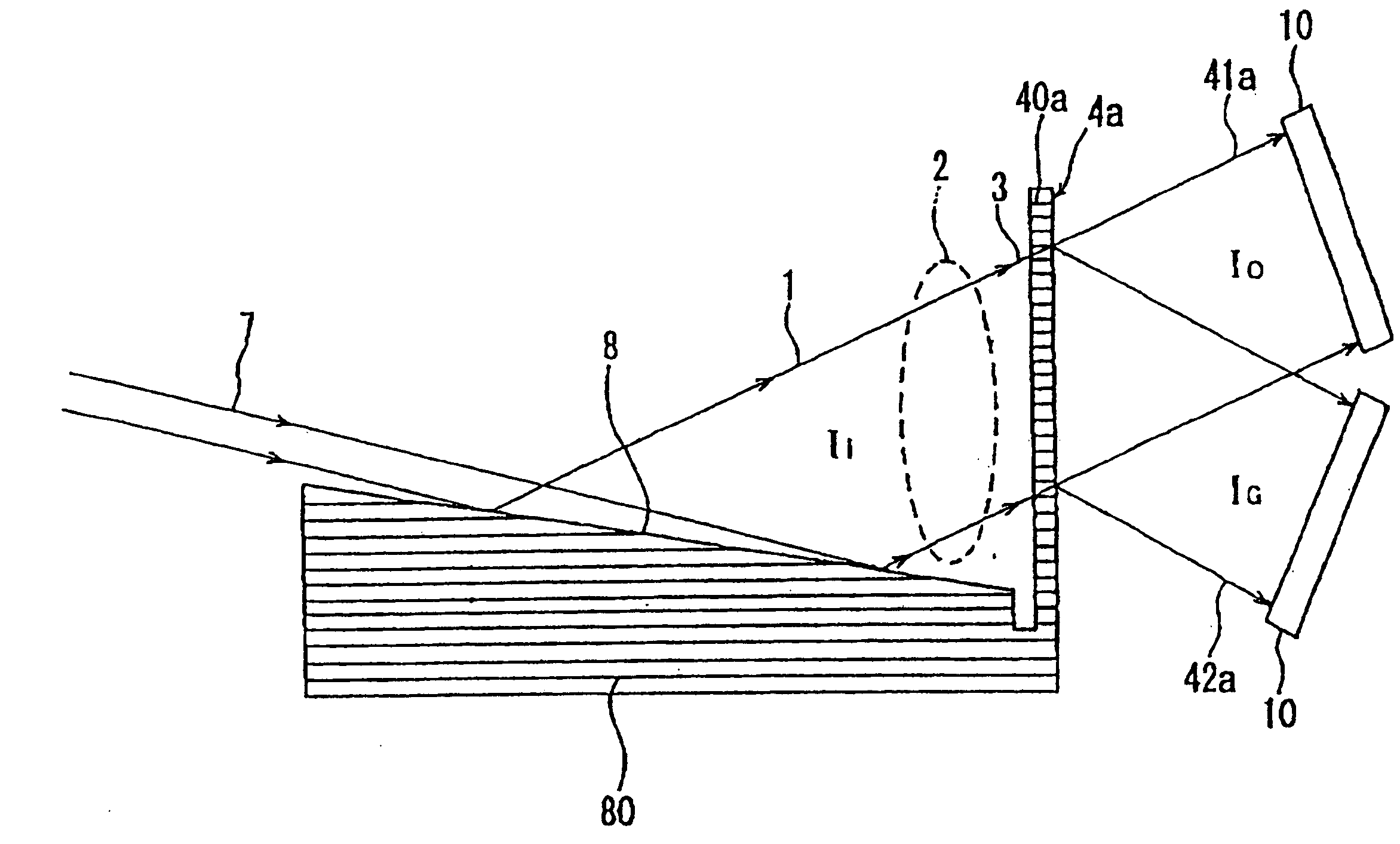
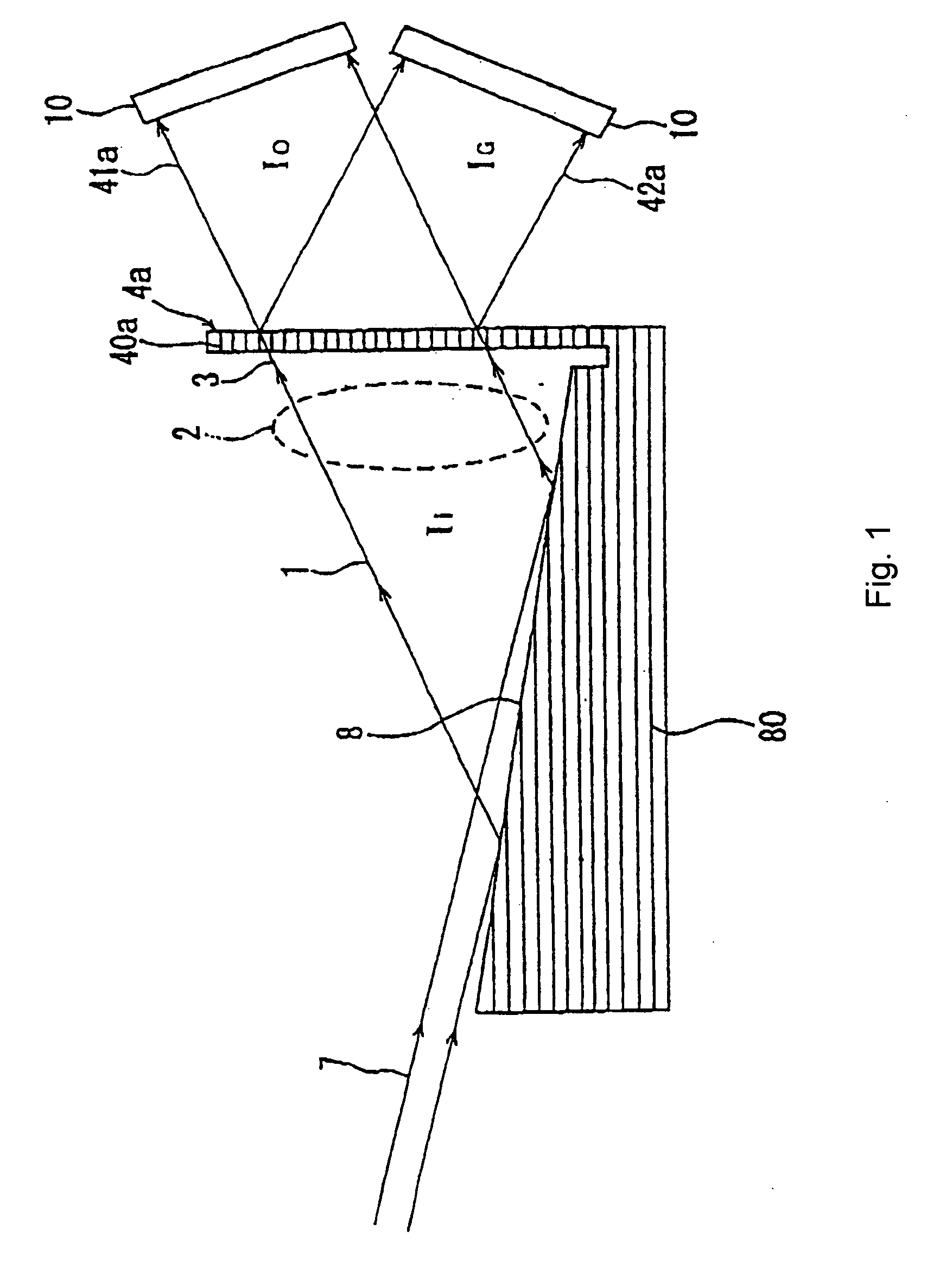
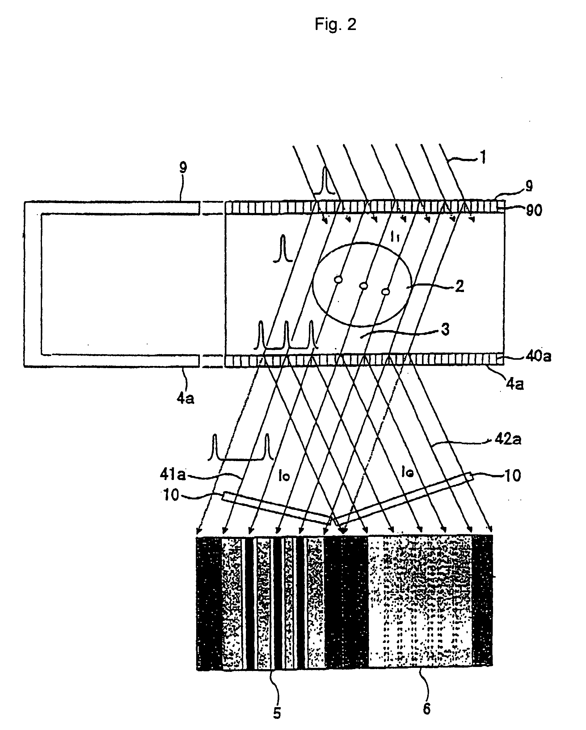
[0076]The invention of this application uses, for example, monochromators or asymmetric monochromators as pre crystal devices which serve as monochromatization and parallelization means. In this case, it is predicated that the monochromators or asymmetric monochromators are arranged with their atomic lattice planes in parallel with the atomic lattice planes of a transmission-type analyzer crystal (4a) or a reflection-type analyzer crystal (4b), so that an achromatic condition (the condition for simultaneous diffraction in all the wavelengths including an accompanying wavelength distribution Δλ of the wavelength λ of the monochromatic X-rays) is satisfied to reduce the angular distribution of the resulting diffraction X-rays as much as possible for increased angular sensitivity (which refers to a difference of relative magnitude of the angular distribution of X-rays obtained from the X-rays from the object with respect to the angular distribution of the monochromatic parallel X-rays ...

second embodiment

[0098]Now, in the case of a reflection-type analyzer crystal, it is publicly known that an X-ray bright-field image is obtained since monochromatic parallel X-rays passing through an object without causing reaction with the object are reflected by the reflection-type analyzer crystal on the one hand while X-rays from the object are observed at the same time. The present invention consists in that an X-ray dark-field image is obtained for situations where monochromatic parallel X-rays passing through an object without causing reaction with the object are reflected, not transmitted, by the reflection-type analyzer crystal on the one hand while X-rays from the object are transmitted by the reflection-type analyzer crystal in the transmission direction and observed on the other hand.

[0099]For example, as illustrated in FIGS. 8(a), 8(b), and 9, when a reflection-type analyzer crystal (4b) is used, an object (2) to be analyzed is irradiated with monochromatic parallel X-rays Ii (1) via an...

third embodiment

[0112]In the first embodiment and second embodiment described above, the X-rays from the transmission-type analyzer crystal (4a) or the reflection-type analyzer crystal (4b) are detected by the X-ray detecting devices (10). These X-ray detecting devices (10) may be flat-type panels, columnar panels, or the like based on two-dimensional detectors (such as an X-ray film, a nuclear plate, an X-ray image pick-up tube, an X-ray fluorescence multiplier tube, an X-ray image intensifier, an X-ray imaging plate, an X-ray CCD, and an X-ray imaging detector by amorphous element), or line sensor one-dimensional detectors.

[0113]Which X-ray detecting devices (10) to use may be selected arbitrarily depending on the type, condition, and the like of the object (2) to be analyzed. In addition, combination scanning of, for example, object movement, rotation, tilt, etc., with the line sensor one-dimensional detectors or two-dimensional detectors is useful for the creation of tomography and stereography...


PUM

PropertyMeasurementUnit
thicknessesaaaaaaaaaa
wavelengthaaaaaaaaaa

Abstract

Non-destructive analysis is carried out by irradiating an object with X-rays, for example, so that the X-rays from the object are incident on an analyzer crystal. The analyzer crystal can be of a transmission-type or a reflection-type. A pre-crystal device is used to make the radiation monochromated and parallelized. Atomic lattice planes of the pre-crystal device are approximately parallel with the atomic lattice planes of the analyzer crystal so as to use the angular analysis capability of the analyzer crystal. The thickness of the analyzer crystal is fixed. For example, for a transmission-type analyzer crystal, the thickness is such that irradiation with monochromatic parallel X-rays in the absence of the object results in a condition in which either one of (a) X-rays along a forward diffraction direction and (b) X-rays along a diffraction direction obtained by dynamical diffraction by the transmission type analyzer crystal have an intensity of nearly zero as compared to the intensity of the other with respect to the monochromatic parallel X-rays. At least one or both of an X-ray dark-field image and an X-ray bright-field are obtained.

Description

[0001]This application is a continuation application of Ser. No. 10 / 483,399, which is the National Stage of International Application No. PCT / JP02 / 06595, filed Jun. 28, 2002.TECHNICAL FIELD[0002]The invention relates to a nondestructive analysis method, a nondestructive analysis device, and a specific object by analyzed the method / device.BACKGROUND ART[0003]With conventional transmission X-rays, the contrast of a resulting image depends on the magnitude of absorption of the X-rays by the object. Namely, if there is a region where the elements, structures, and densities of substances with high X-ray absorptance are dense, that portion exhibits a low transmittance and can be caught as a dark shadow in an image.[0004]There is also a recently known method of capturing the state of refraction of X-rays dependent on the elements, structures, and densities of substances, not the absorption of X-rays. Monochromatic parallel X-rays have a wave front (X-rays are plane waves) which varies with...

Claims


Application Information

Patent Timeline
Patent Type & Authority Applications(United States)
IPC IPC(8): G01N23/207G01N23/04G01N23/20
CPCG01N23/04G01N23/207
Inventor ANDO, MASAMI
Owner ANDO MASAMI
Why Eureka
Try Eureka