Inlet air conditioning system

a technology of inlet air conditioning and turbine, which is applied in the direction of domestic cooling apparatus, combustion air/fuel air treatment, lighting and heating apparatus, etc., can solve the problems of low turbine efficiency and power output, the inability to retrofit the gas turbine, and the exorbitant cost of retrofitting the inlet system, etc., to achieve the effect of increasing the efficiency of the turbomachin

Inactive Publication Date: 2008-12-04
GENERAL ELECTRIC CO
View PDF2 Cites 36 Cited by
  • Summary
  • Abstract
  • Description
  • Claims
  • Application Information

AI Technical Summary

Benefits of technology

[0010]In an embodiment of the present invention, a system for increasing the efficiency of a turbomachine comprising an inlet system and a compressor, the system comprising: a housing configured to channel an airstream towards the inlet system; wherein the housing is positioned upstream of the inlet system; and at least one conditioning module configured for adjusting the temperature of the airstream; wherein the airstream enters the conditioning module at a first temperature and exits the conditioning module at a second temperature.

Problems solved by technology

The higher the inlet system pressure drop, the lower the efficiency and power output of the turbine.
However, these operators may resist retrofitting the gas turbine for a few reasons including operational downtime and construction costs.
Gas turbine operators greatly avoid shutting down the machines because of the associated loss in revenue.
Also, the cost of retrofitting an inlet system can be exorbitant.
The downtime, lost revenues, and construction costs prohibit operators from adding an air conditioning system.

Method used


Image

  • Inlet air conditioning system
  • Inlet air conditioning system
  • Inlet air conditioning system

Examples


Embodiment Construction

[0016]The following detailed description of preferred embodiments refers to the accompanying drawings, which illustrate specific embodiments of the invention. Other embodiments having different structures and operations do not depart from the scope of the present invention.

[0017]Certain terminology may be used herein for the convenience of the reader only and is not to be taken as a limitation on the scope of the invention. For example, words such as “upper”, “lower”, “left”, “right”, “front”, “rear”, “top”, “bottom”, “horizontal”, “vertical”, “tipstream”, “downstream”, “fore”, “aft”, and the like; merely describe the configuration shown in the Figures. Indeed, the element or elements of an embodiment of the present invention may be oriented in any direction and the terminology, therefore, should be understood as encompassing such variations unless specified otherwise.

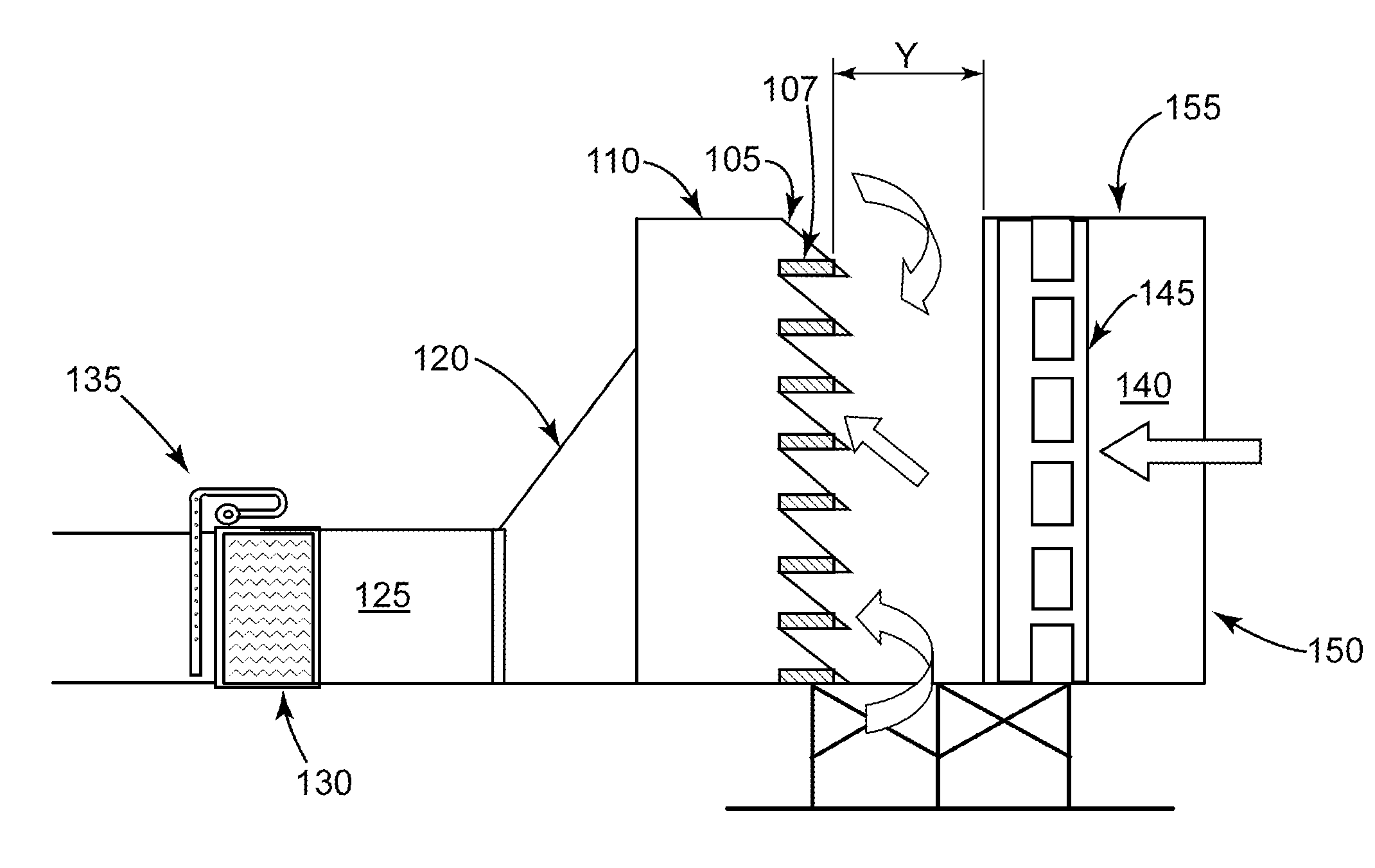
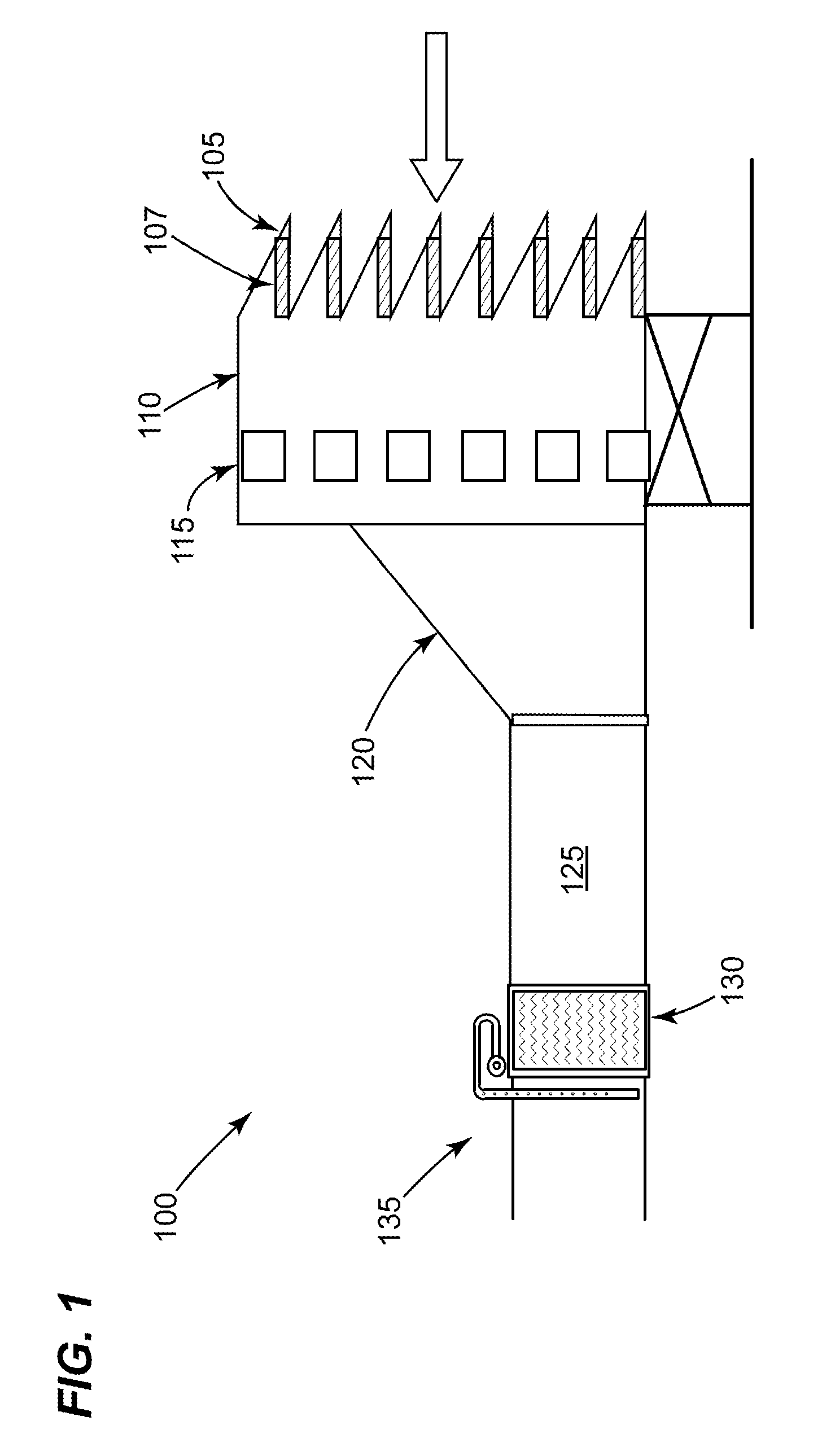
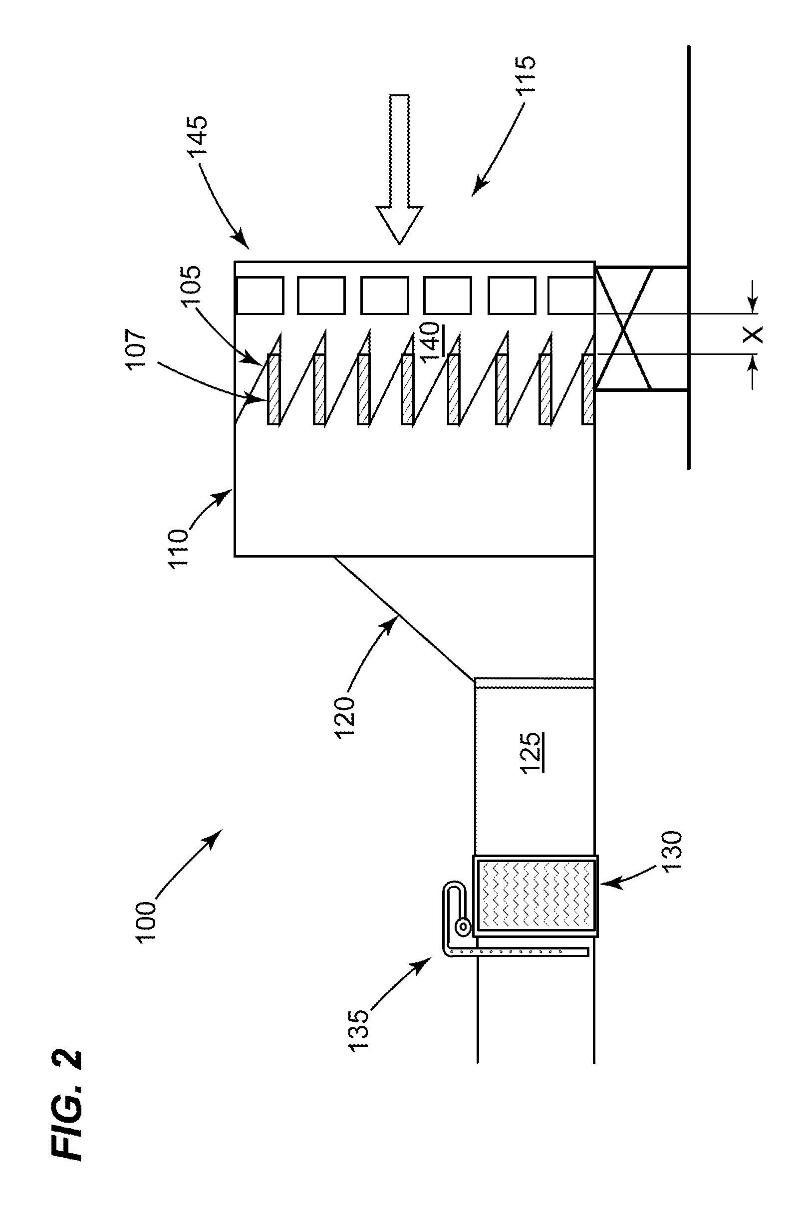
[0018]The present invention provides an air conditioning system located upstream of the inlet system for a gas turbi...


PUM


Abstract

An embodiment of the present invention provides an air conditioning system located upstream of the inlet system for a gas turbine. The air conditioning system may comprise at least one conditioning module for adjusting the temperature of the airstream. The at least one conditioning module may have a plurality of forms including at least one of the following systems: a chiller, an evaporative cooler; a spray cooler, or combinations thereof. The specific form of the at least one conditioning module may be determined in part the configuration of the gas turbine.

Description

[0001]This application is a continuation-in-part of commonly assigned U.S. patent application Ser. No. 11 / 425,520 [GE Docket 204795], filed Jun. 21, 2006.BACKGROUND OF THE INVENTION[0002]The present invention relates generally to a turbomachine; and more particularly to a system for increasing the efficiency of a turbomachine.[0003]Some turbomachines, such as, but not limiting of, a gas turbine, may generally include, in serial flow arrangement, an inlet system for receiving and channeling an ambient airstream; a compressor which receives and compresses that airstream, a combusting system that mixes a fuel and the compressed airstream, ignites the mixture, and allows for the gaseous by-product to flow to a turbine section; which transfers energy from the gaseous by-product to an output power. Other components of the gas turbine may be used therein.[0004]The power output of a gas turbine is directly proportional to and limited by the mass flowrate of compressed airstream exiting the ...

Claims


Application Information

Patent Timeline
Patent Type & Authority Applications(United States)
IPC IPC(8): F01D25/08F25D9/00F25B49/02F25B41/00
CPCF02C7/04F02C7/057F02C7/143
Inventor CHILLAR, RAHUL J.ROGERS, DAVID L.MOTAKEF, ABBAS
Owner GENERAL ELECTRIC CO
Why Eureka
Try Eureka