Connecting device, transmission, power output apparatus including the transmission, and method of controlling connecting device

a technology of connecting device and power output device, which is applied in the direction of propulsion parts, propulsion using engine-driven generators, process and machine control, etc., can solve the problems of difficult to determine whether the fixed dog or the moving dog cannot be easily engaged, and the transmission of power is selective and efficient, so as to facilitate and smoothly switch, facilitate and smoothly realize the transmission of power, and facilitate the effect of selective and efficient transmission

Inactive Publication Date: 2008-12-04
TOYOTA JIDOSHA KK
View PDF4 Cites 35 Cited by
  • Summary
  • Abstract
  • Description
  • Claims
  • Application Information

AI Technical Summary

Benefits of technology

[0006]A main object of the present invention is to easily and smoothly connect a first element and a second element in a connecting device including an engaging element mounted on each of the first and second elements and having a plurality of teeth and a movable engaging member having a plurality of teeth meshed with a plurality of teeth of both engaging elements.
[0025]The first and second engaging elements can be smoothly engaged, even when the plurality of teeth of the movable engaging member are unable to appropriately mesh with the plurality of teeth of the other of the first and second engaging elements, by moving the movable engaging element to the other of the first and second engaging elements when the deviation of the rotation speed of the second element from the rotation speed of the first element matches the predetermined target deviation and by pressing the movable engaging element against the other of the first and second engaging elements to cause the plurality of teeth of the movable engaging member to appropriately mesh with the plurality of teeth of the other of the first and second engaging elements. Controlling the drive unit for the predetermined time so that the movable engaging element moves toward the other of the first and second engaging elements enables to complete the connection of the first element and the second element without determining whether the movable engaging element has completely engaged with both of the first and second engaging elements. Therefore, the method of controlling the connecting device can easily and smoothly connect the first element and the second element with relatively simple control.

Problems solved by technology

However, the movable dog and the fixed dog may not be able to smoothly engage if the dog teeth of the movable dog and the dog teeth of the fixed dog are not appropriately meshed when the rotation of the movable dog is stopped.
However, in practice, it is not easy to determine whether the dog teeth of two dogs to be connected are appropriately meshed with each other.

Method used


Image

  • Connecting device, transmission, power output apparatus including the transmission, and method of controlling connecting device
  • Connecting device, transmission, power output apparatus including the transmission, and method of controlling connecting device
  • Connecting device, transmission, power output apparatus including the transmission, and method of controlling connecting device

Examples


Embodiment Construction

[0059]The best mode for implementing the present invention will now be described using the embodiments.

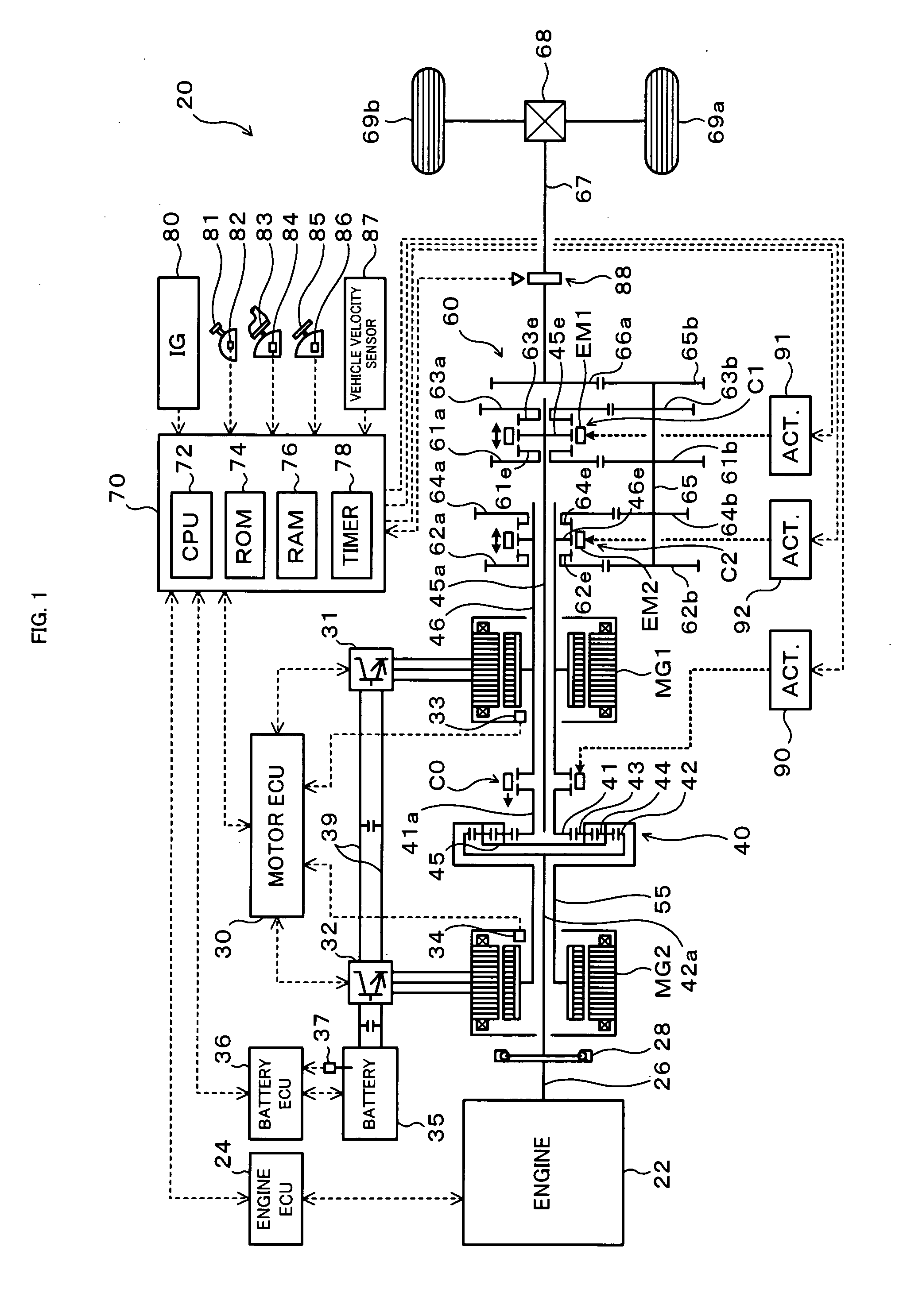
[0060]FIG. 1 is a schematic configuration diagram of a hybrid vehicle 20 provided with a transmission including a connecting device according to an embodiment of the present invention. The hybrid vehicle 20 shown in FIG. 1 is configured as a rear wheel drive vehicle and includes, for example: an engine 22 mounted on the vehicle front part; a power distribution and integration mechanism (differential rotation mechanism) 40 connected to a crankshaft (engine shaft) 26 of the engine 22; a motor MG1 connected to the power distribution and integration mechanism 40 and capable of generating electricity; a motor MG 2 arranged coaxially with the motor MG 1, connected to the power distribution and integration mechanism 40, and capable of generating electricity; a transmission 60 capable of shifting power from the power distribution and integration mechanism 40 and transmitting the power to a...


PUM


Abstract

A motor MG1 is controlled so that the rotation speed deviation of the rotation speed of a first motor shaft 46 from the rotation speed of a second gear 62a matches a predetermined target rotation speed deviation and an actuator 92 is controlled so that a movable engaging member EM2 moves toward an engaging portion 62e for a predetermined time after the rotation speed has matched the target rotation speed deviation, if, for example, the movable engaging member EM2 is to be engaged with both of an engaging portion 46e and the engaging portion 62e of the second gear 62a to connect the first motor shaft 46 and the second gear 62a when the movable engaging member EM2 is engaged only with the engaging portion 46e of the first motor shaft 46.

Description

BACKGROUND OF THE INVENTION[0001]1. Field of the Invention[0002]The present invention relates to a connecting device capable of connecting two elements, a transmission, a power output apparatus including the transmission, and a method of controlling the connecting device.[0003]2. Description of the Prior Art[0004]Conventionally, a front-rear wheel drive vehicle has been known in which the front wheels are driven by an engine while the rear wheels are driven by a motor through a dog clutch (see, for example, Japanese Patent Laid-Open No. 2001-1779). In the front-rear wheel drive vehicle, once the rear wheels follow and the movable dog of the dog clutch rotates against the fixed dog upon the start of the vehicle using power from the engine, rotation of the movable dog is stopped by driving the motor at a predetermined target rotation speed corresponding to the wheel speed of the rear wheels to engage the movable dog to the fixed dog. In the front-rear wheel drive vehicle, the motor ro...

Claims


Application Information

Patent Timeline
Patent Type & Authority Applications(United States)
IPC IPC(8): B60W20/00F16H59/74B60K6/36B60K6/387B60K6/445B60K6/547B60L15/20B60L50/16B60W10/02B60W10/06B60W10/08B60W10/10F16H3/72
CPCB60L2240/421B60W10/08B60W10/11B60W30/19B60W2710/081F16H3/006F16H61/0403F16H2003/0811F16H2061/0422Y02T10/642Y02T10/7258B60L15/20B60L2240/423B60L2240/441B60L2240/443B60L2240/486B60L2240/507B60L2250/24B60L2250/26B60L50/61B60L50/16B60L58/12Y02T10/62Y02T10/64Y02T10/70Y02T10/7072Y02T10/72
Inventor KATSUTA, HIROSHIOBA, HIDEHIRO
Owner TOYOTA JIDOSHA KK
Why Eureka
Try Eureka