
Methods and apparatus for depositing a uniform silicon film with flow gradient designs

a flow gradient and silicon film technology, applied in lighting and heating apparatus, combustion types, coatings, etc., can solve the problems of significant challenge in producing large and efficient solar cells, increasing the difficulty of maintaining a uniform plasma and/or process gas flow over the surface area of increasingly larger substrates, and increasing the difficulty of achieving uniform flow gradients

Inactive Publication Date: 2008-12-11
APPLIED MATERIALS INC
View PDF8 Cites 385 Cited by
  • Summary
  • Abstract
  • Description
  • Claims
  • Application Information

AI Technical Summary

Benefits of technology

[0011]In yet another embodiment, an apparatus for depositing a uniform film for solar cell applications may include a processing chamber, and a gas distribution plate disposed in the processing chamber having a plurality of chokes formed therethrough, the chokes arranged to define at least three different zones of flow resistance, wherein a first zone defined in the corners of the gas distribution plate has a flow resistance greater than a flow resistance of a second zone defined along the edge of the gas distribution plate, and a third zone defined in the center of the gas dis

Problems solved by technology

As the demand for larger solar cell substrates continues to grow, maintaining a uniform plasma and / or process gas flow during a PECVD process over the surface area of increasingly larger substrate has become increasingly difficult.
Film property variation between the center and edge portions of deposited films present a significant challenge for producing large and efficient solar cells.
With ever-increasing substrate size, edge to center property variation has become more problematic.

Method used


Image

  • Methods and apparatus for depositing a uniform silicon film with flow gradient designs
  • Methods and apparatus for depositing a uniform silicon film with flow gradient designs
  • Methods and apparatus for depositing a uniform silicon film with flow gradient designs

Examples


Embodiment Construction

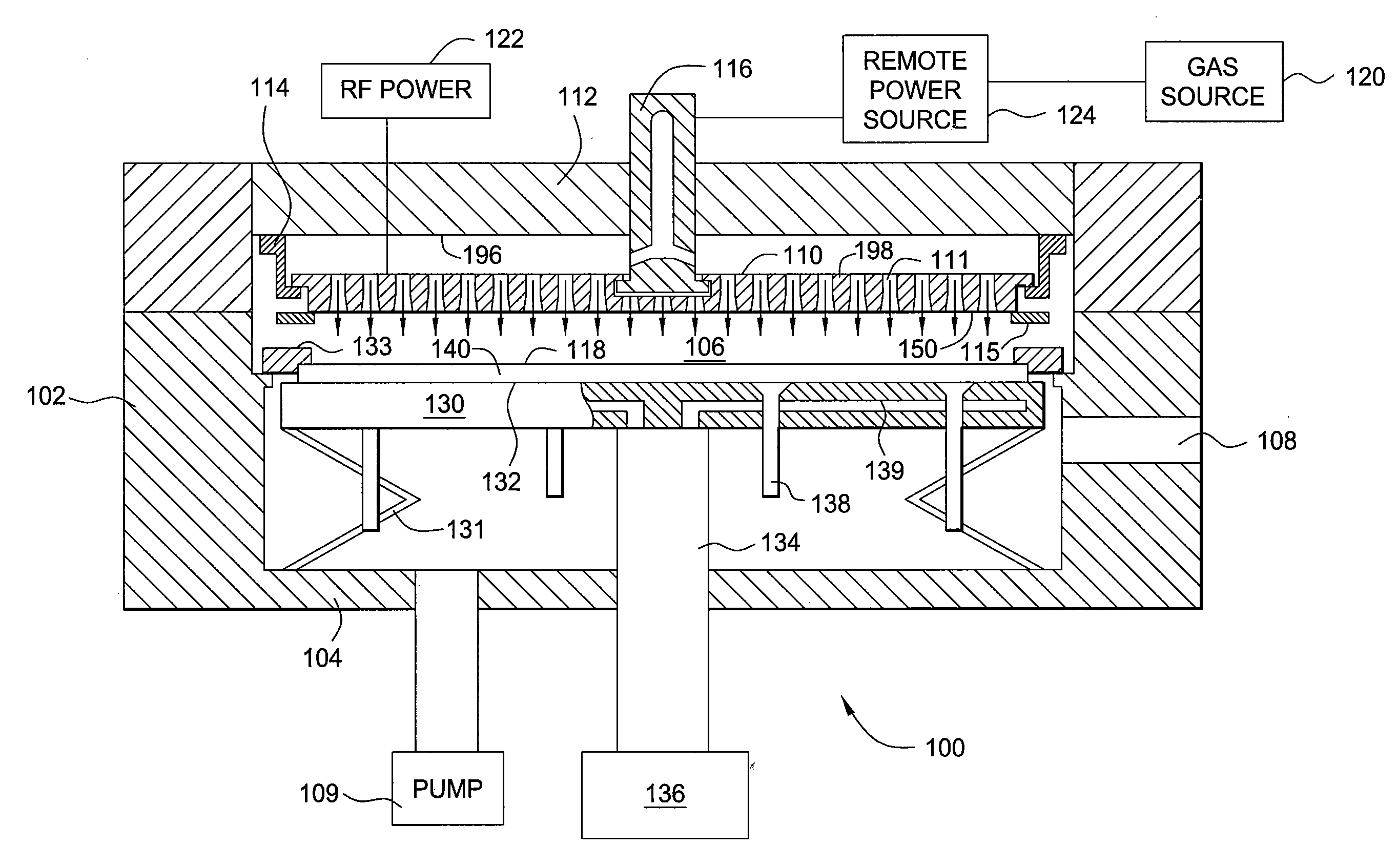
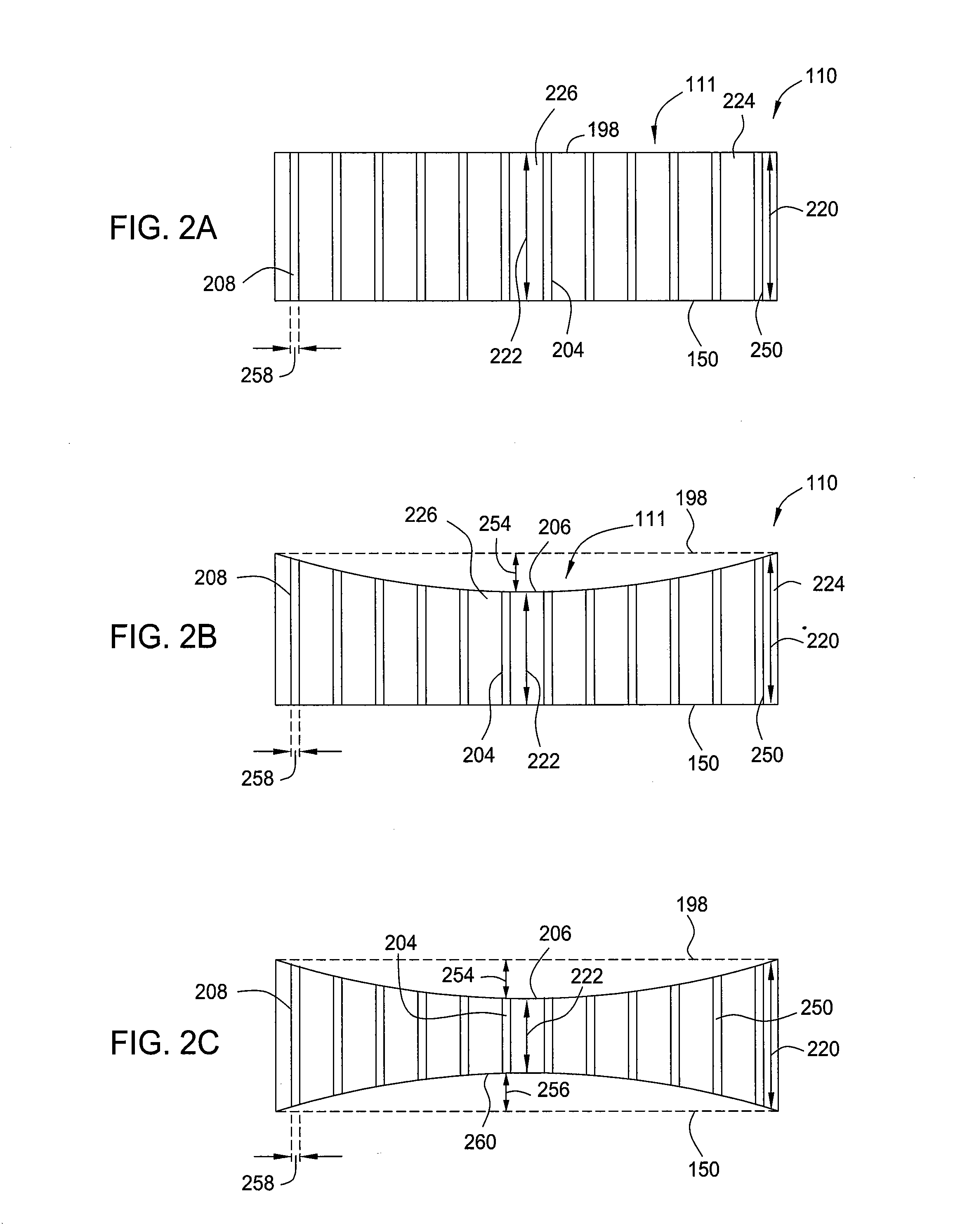
[0035]Methods and apparatus for depositing a silicon film suitable for solar cell applications are provided. In one embodiment, the apparatus includes a gas distribution plate having different choke lengths to create a gradient of gases flowing toward a substrate. The flow gradient created by the gas distribution plate provides a flexible control of edge to corner distribution of process gases provided through the gas distribution plate to the substrate surface. The controlled distribution of gases across a substrate enhances the ability to adjust thickness and / or profile of films deposited on the substrate. The flow gradient created by different choke lengths in the gas distribution plate also provides a process control attribute which facilitates controlling film property variation over the width of the substrate.

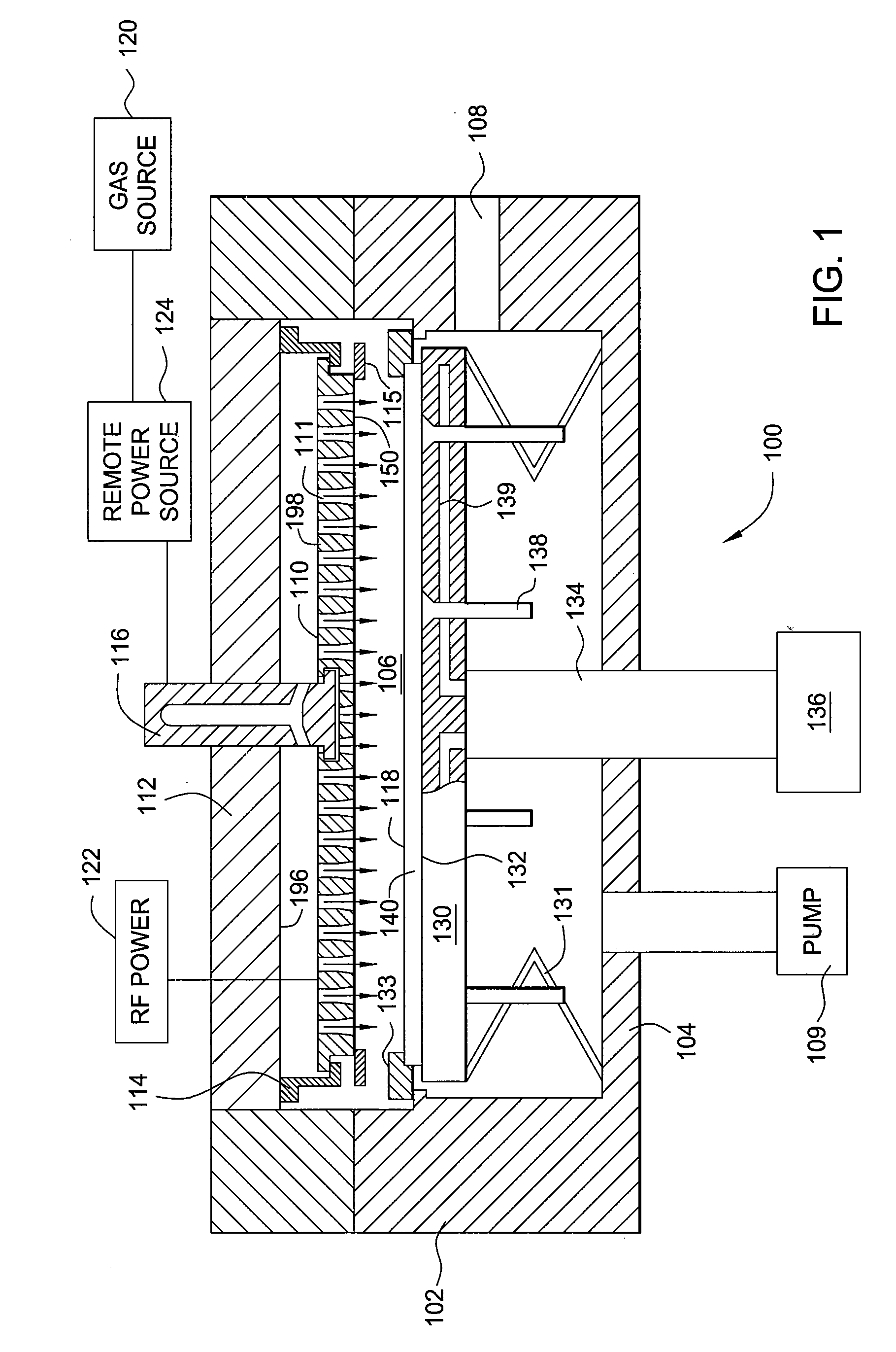
[0036]FIG. 1 is a schematic cross-section view of one embodiment of a plasma enhanced chemical vapor deposition (PECVD) chamber 100 in which one or more films suitable fo...


PUM


Abstract

Methods and apparatus having a flow gradient created from a gas distribution plate are provided. In one embodiment, the method and apparatus are particularly useful for, but not limited to, depositing a silicon film for solar cell applications. The apparatus for depositing a uniform film for solar cell applications includes a processing chamber, and a quadrilateral gas distribution plate disposed in the processing chamber and having at least four corners separated by four sides. The gas distribution plate further includes a first plurality of chokes formed through the gas distribution plate, the first plurality of chokes located in the corners, and a second plurality of chokes formed through the gas distribution plate, the second plurality of chokes located along the sides of the gas distribution plate between the corner regions, wherein the first plurality of chokes have a greater flow resistance than that of the second plurality of chokes.

Description

CROSS-REFERENCE TO OTHER APPLICATIONS[0001]This application is related to U.S. patent application Ser. No. 11 / 759,542, entitled “AN APPARATUS FOR DEPOSITING A UNIFORM SILICON FILM AND METHODS FOR MANUFACTURING THE SAME”, filed Jun. 7, 2007, (Attorney Docket No. APPM / 11707) which is herein incorporated by reference.BACKGROUND OF THE DISCLOSURE[0002]1. Field of the Invention[0003]Embodiments of the invention generally relate to a gas distribution plate assembly and method for manufacturing the same in a processing chamber.[0004]2. Description of the Background Art[0005]Photovoltaic (PV) devices or solar cells are devices which convert sunlight into direct current (DC) electrical power. PV or solar cells typically have one or more p-i-n junctions. Each junction comprises two different regions within a semiconductor material where one side is denoted as the p-type region and the other as the n-type region. When the p-i-n junction of the PV cell is exposed to sunlight (consisting of ener...

Claims


Application Information

Patent Timeline
IPC IPC(8): C23C16/00B05B1/14
CPCC23C16/24C23C16/45565C23C16/5096H01J37/32449C23C16/455C23C16/4583
Inventor CHOI, SOO YOUNGWON, TAE KYUNGWHITE, JOHN M.
Owner APPLIED MATERIALS INC
Learn More