
Lightweight tent

Inactive Publication Date: 2008-12-11
STEWART JEFFREY L
View PDF14 Cites 10 Cited by
  • Summary
  • Abstract
  • Description
  • Claims
  • Application Information

AI Technical Summary

Benefits of technology

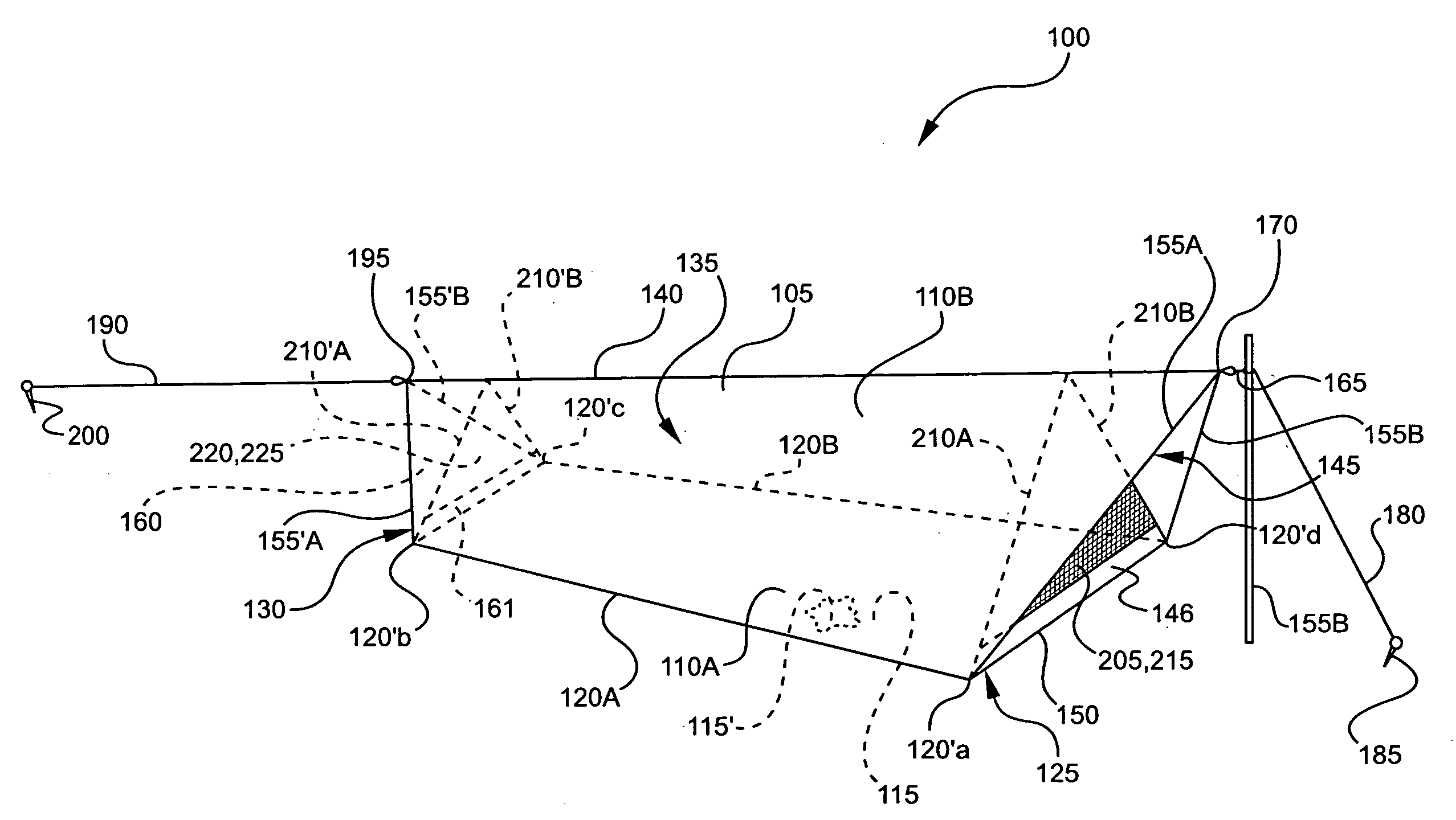
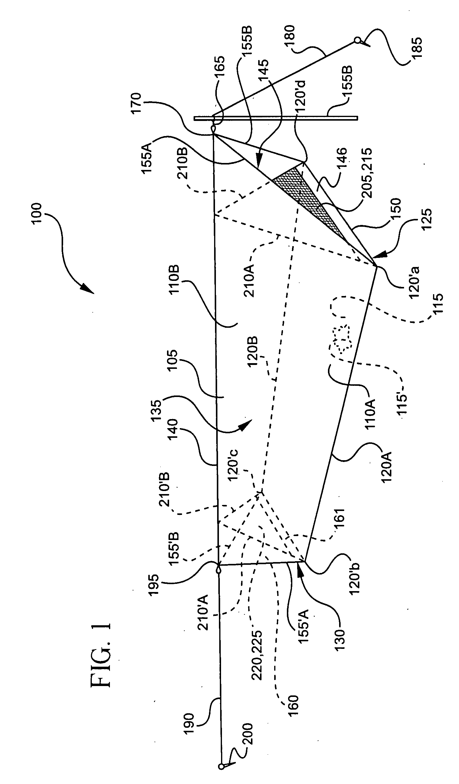
[0004]The present invention is a lightweight tent having a sloping roof that overhangs the front door entrance, and preferably the tent's base at least at one end, allowing the tent to be erected using a single supporting member, such as a pole, while providing good ventilation and full protection from the elements and insects.
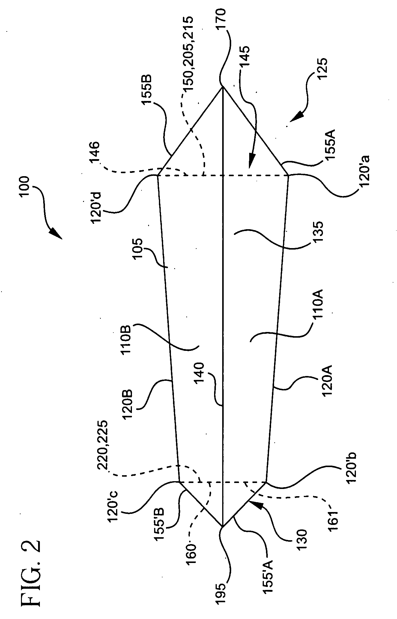
[0005]In one embodiment, the tent is constructed from a waterproof canopy having generally trapezoidal sides joined to a floor that preferably tapers from the front to the rear. The tent has a roof ridgeline that slopes downward from the tall front to a shorter rear, thereby forming a funnel shaped region within the tent. This funnel shaped interior maximizes convective air flow by forcing moisture out a top opening at the front end as cooler air enters low at the rear end. The roof ridgeline is longer than the floor and the front edges of the roof tilt toward the ridgeline at an angle less than ninety degrees allowing the roof to overhang the front door entrance, and preferably the floor as well. The resulting overhang produces an awning that prevents rain, snow and other elements from entering the tent. Similarly, the rear edges of the roof tilt toward the ridgeline, allowing the roof to likewise overhang the floor and door at the rear.
[0007]In another embodiment, the tent includes sidewalls to increase the useable floor space. At the front end, the bottom of the overhang starts at the top of the sidewalls to achieve a more taut structure without the use of additional stakes. Similarly, the overhang starts at the top of the sidewalls at the rear end.

Problems solved by technology

Currently available tents, however, all have trade-offs.
Those providing the best protection from the environment are, for most backpackers, too heavy.
Most lightweight tents, on the other hand, generally do not provide adequate protection on all sides from insects or the elements, e.g., wind, rain, sleet, hail and snow.
And, those tents that do, typically suffer from poor ventilation, allowing condensation to collect inside.

Method used


Image

  • Lightweight tent
  • Lightweight tent
  • Lightweight tent

Examples


Embodiment Construction

[0015]A lightweight tent for use in backpacking and other outdoor activities that maximizes ventilation as well as protection from the elements and insects, all with a minimal amount of materials and weight, and with a minimal amount of required assembly, is realized by employing a sloping roof that overhangs the door, and preferably the tent's base as well at one or both ends. Additionally, the tent has door flap(s) that open from the top down. Importantly, the sloped, overhanging roof allows the tent to be erected using a single supporting member, such as a pole, while providing good ventilation and protection from the elements.

[0016]Without any loss of generality or applicability for the principles of the invention, the preferred embodiment of the lightweight tent is described with a sloping roof ridgeline that is straight. It should be clearly understood, however, that the present invention is equally applicable to other roof line shapes, such as catenary roof ridgelines, and th...


PUM


Abstract

The present invention is a lightweight tent having a sloping roof that overhangs the door and preferably the base of the tent as well at one or both ends. This latter slope allows the tent to be erected using a single supporting member, and provides good ventilation while simultaneously providing good protection from the elements. The lightweight tent is constructed from a waterproof canopy having generally trapezoidal sides joined to a floor that preferably tapers from the front to the rear. Its roof slopes downward from the front to the rear, with at least its front side edges tilting toward the ridgeline at an angle less than ninety degrees.

Description

TECHNICAL FIELD[0001]The present invention generally relates to tents and shelters used in backpacking and other outdoor activities.BACKGROUND OF THE INVENTION[0002]Tents are typically used by backpackers, hikers and others as shelters during overnight trips, and need to be as light and compact as possible to make them easier to carry. Moreover, they need to protect the backpacker(s) from the weather, and from insects, while also providing adequate ventilation to minimize condensation. Additionally, tents need to be sturdy, and should be fast and easy to erect, preferably using as few custom poles and stakes as possible.[0003]To date, there are many tents available for use as shelters. Currently available tents, however, all have trade-offs. Those providing the best protection from the environment are, for most backpackers, too heavy. Most lightweight tents, on the other hand, generally do not provide adequate protection on all sides from insects or the elements, e.g., wind, rain, s...

Claims


Application Information

Patent Timeline
IPC IPC(8): E04H15/04
CPCE04H15/04E04H2015/328
Inventor STEWART, JEFFREY L.
Owner STEWART JEFFREY L
Learn More