Buck-boost converter

a converter and buckboost technology, applied in the direction of dc-dc conversion, power conversion systems, instruments, etc., can solve the problems of reducing the efficiency of the converter considerably, requiring a larger inductor, and not being attractive to the eye, so as to achieve constant output voltage and high efficiency, without affecting efficiency

Active Publication Date: 2008-12-11
CIRRUS LOGIC INC
View PDF13 Cites 44 Cited by
  • Summary
  • Abstract
  • Description
  • Claims
  • Application Information

AI Technical Summary

Benefits of technology

[0024]An embodiment of the present invention can provide a constant frequency current-mode buck-boost converter which is able to provide a constant output voltage while maintaining a high efficiency with input voltages that are higher, lower or equal to the input voltage. It does not need any extra components to do that and senses the curren...

Problems solved by technology

Not only does that reduce the efficiency of the converter considerably, in comparison with a simple buck or boost converter, but it also requires a larger inductor due to the larger peak current.
This makes th...

Method used


Image

  • Buck-boost converter
  • Buck-boost converter
  • Buck-boost converter

Examples


Embodiment Construction

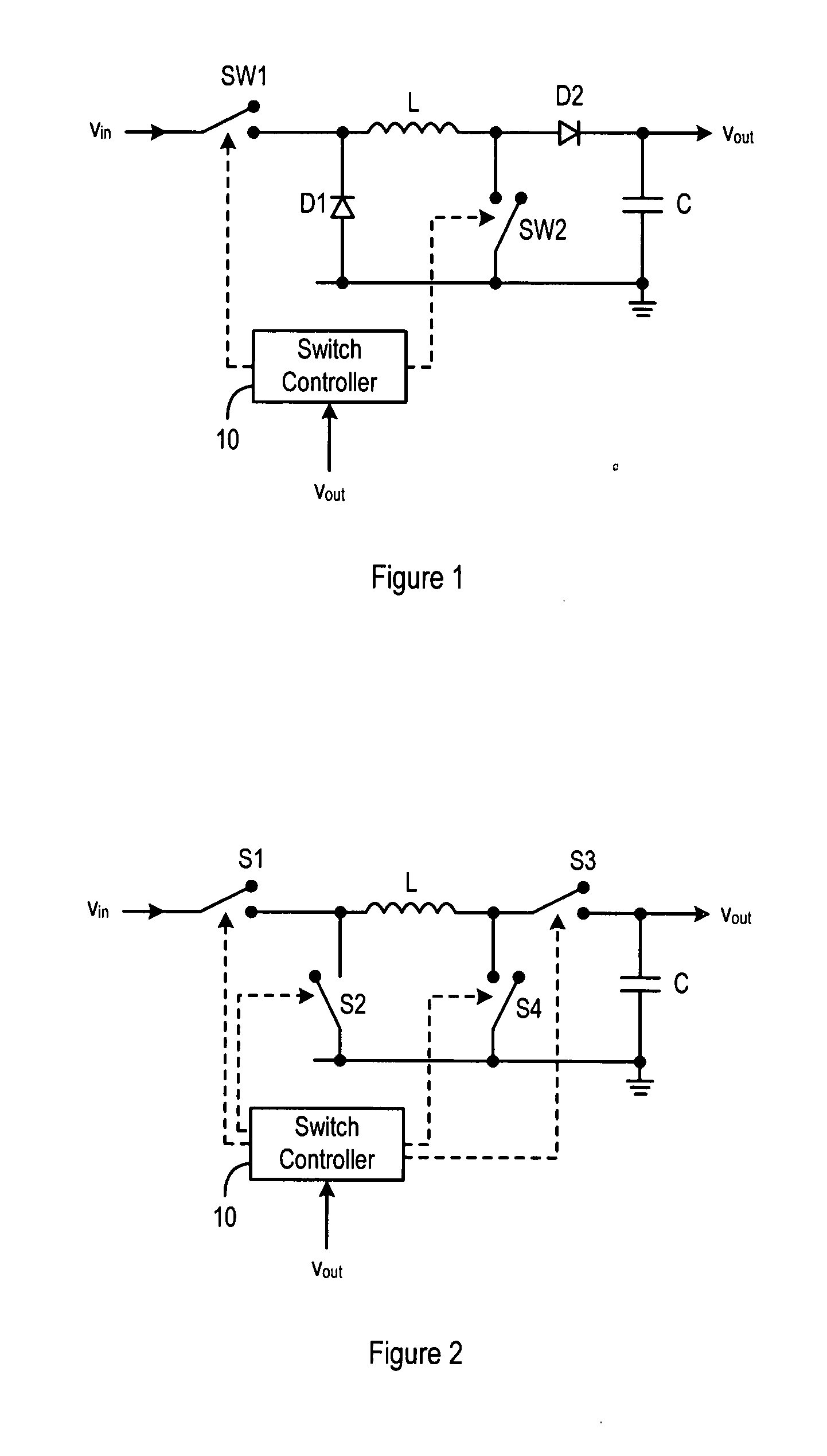
[0038]Embodiments of the present invention will now be described with reference to a four-switch type buck-boost converter as shown in FIG. 2. This buck-boost converter is modified from that shown in FIG. 1 in that the two diodes D1 and D2 of FIG. 1 are replaced by switches. Thus, the switches labelled S1, S2, S3 and S4 in FIG. 2 correspond to SW1, D1, D2 and SW2 of FIG. 1 respectively. In this case, S2 and S3 can be viewed as synchronous rectifiers.

[0039]The present invention can be applied to either configuration of buck-boost converter shown in FIG. 1 or FIG. 2. It is also possible to configure a buck-boost converter with three switches and one diode; for example, S3 of FIG. 2 could be replaced by a diode. The switch or the diode located in the positions of D1 and D2 in FIG. 1 may collectively be referred to as a current control means. MOS transistors, the gates of which are coupled to the switch controller 10 for receiving control signals, are preferably employed as the switches...


PUM


Abstract

A controller (10) for a constant frequency current-mode buck-boost converter, the converter including an inductor (L), a first switch (SW1, S1) connected between an input terminal (Vin) of the converter and one end of the inductor (L), a diode or a switch (D1, S2), connected between the first end of the inductor and ground, a second diode or switch (D2, S3) connected between a second end of the inductor and an output terminal (Vout) of the converter, and a second switch (SW2, S4) coupled between the other end of the inductor and ground. A current sensor is also present for sensing current in the first switch (SW1, S1) as a measure of the inductor (L) current. The controller (10) comprises a feedback circuit for deriving a feedback signal from the output terminal (Vout) and a waveform generator (31, 32) for generating buck and boost slope compensation ramps (RMP-BUCK, RMP-BOOST) used for improving stability of operation in both buck and boost operating modes of the converter. Control logic in the controller (10) generates drive signals during every clock period to repeatedly open and close the switches at individual duty cycles determined on the basis of the feedback signal, the sensed current signal and the slope compensation ramps. The buck and boost slope compensation ramps are mutually offset with respect to one another in time, for example by 50% of a clock cycle, and the control logic uses the sensed current signal only while the first switch (SW1, S1) is closed, thus avoiding the need for additional current sensing circuitry.

Description

[0001]The present invention relates to buck-boost converters and controllers for the same, as well as to a method of controlling a buck-boost converter. More particularly, the present invention concerns constant-frequency current-mode buck-boost converters.BACKGROUND OF THE INVENTION[0002]Buck-boost converters are gaining in popularity. Recent applications include portable media players featuring hard disk drives that require a supply voltage of typically 3.3V where output voltages of the batteries most commonly used in portable devices are ranging from 4.2V down to below 3.0V. To be able to make the most of the batteries it is apparent that a voltage regulator is needed that can generate a supply voltage for such components that can either be below, above or equal to the battery voltage. A buck-boost converter does just that.[0003]Buck-boost converters have been known for a long time. A simple non-inverting type converter consists of two switches, two diodes, some sort of modulator...

Claims


Application Information

Patent Timeline
IPC IPC(8): G05F1/00G05F1/44
CPCH02M3/1582G05F1/62
Inventor HAIPLIK, HOLGER
Owner CIRRUS LOGIC INC
Why Eureka
Try Eureka