Image Coding Method, Image Coding Apparatus, Image Decoding Method and Image Decoding Apparatus

Inactive Publication Date: 2008-12-11
HITACHI LTD
View PDF4 Cites 6 Cited by
  • Summary
  • Abstract
  • Description
  • Claims
  • Application Information

AI Technical Summary

Benefits of technology

[0012]The invention is made in light of the foregoing problem, and an object of the invention is to restrain a d

Problems solved by technology

However, in the case where the Radon transform is used for an image, the size of which is not a prime number, this transform has a property such that the image quality deteriorates when the image is decompressed by an inverse transform.
For this reason, the image quantity of decoded images is insufficient when the Radon transform is used in an image coding system using the blocks having the same size of powers of 2 squared which are not a prime number as an existing coding system has.
Therefore, it is difficult to realize reduction for the amount of code by using the Radon transform.

Method used


Image

  • Image Coding Method, Image Coding Apparatus, Image Decoding Method and Image Decoding Apparatus
  • Image Coding Method, Image Coding Apparatus, Image Decoding Method and Image Decoding Apparatus
  • Image Coding Method, Image Coding Apparatus, Image Decoding Method and Image Decoding Apparatus

Examples


first embodiment

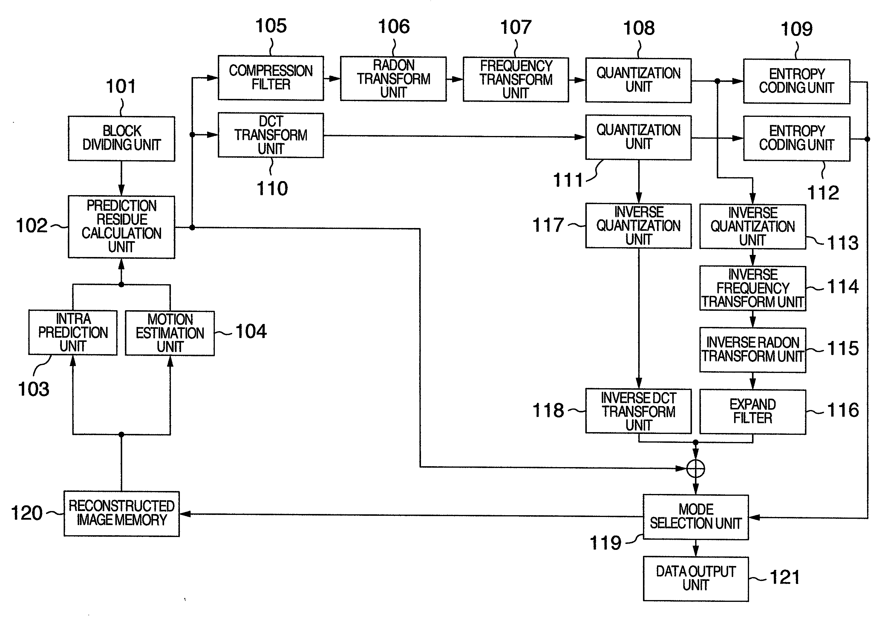
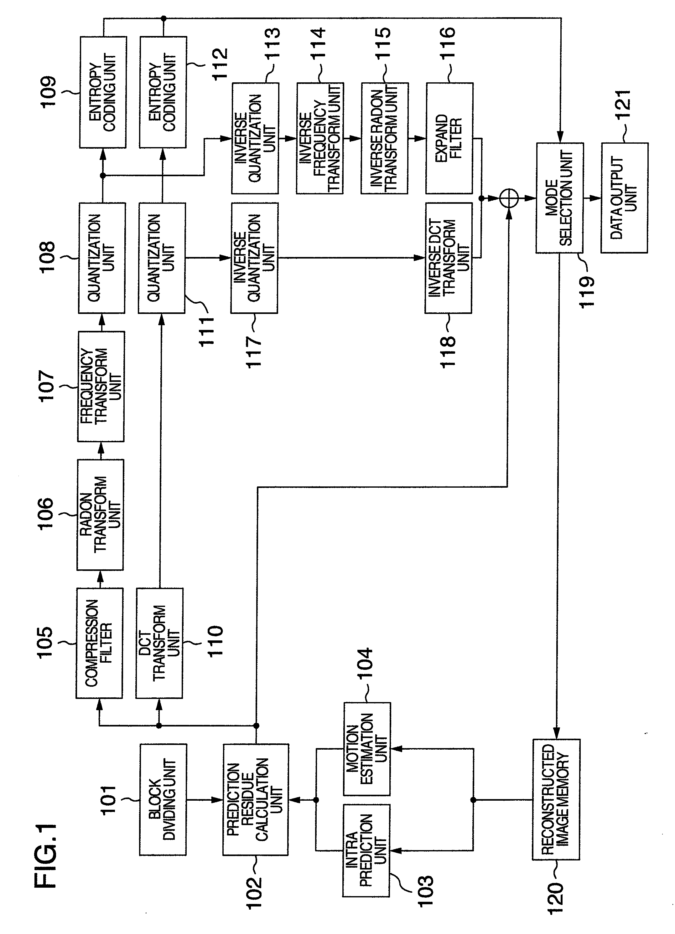
[0029]A first embodiment in the invention will be described with reference to the drawings. FIG. 1 is a block diagram showing an example of an image coding apparatus in relation to the first embodiment.

[0030]The image coding apparatus is constituted by a block dividing unit 101, a prediction residue calculation unit 102, an intra prediction unit 103, a motion estimation unit 104, a size reduction 105, a Radon transform unit 106, a frequency transform unit 107, a quantization unit 108, an entropy coding unit 109, a DCT transform unit 110, a quantization unit 111, an entropy coding unit 112, an inverse quantization unit 113, an inverse frequency transform unit 114, an inverse Radon transform unit 115, an expand filter 116, an inverse quantization unit 117, an inverse DCT transform unit 118, a mode selection unit 119, a reconstructed image memory 120, and a data output unit 121.

[0031]An operation of the respective construction elements in the image coding apparatus will be described be...

second embodiment

[0093]FIG. 7 shows an example of a data recording medium in a second embodiment of the invention.

[0094]A coding stream in the embodiment of the invention is a coding stream generated by the image coding apparatus or image coding method in the first embodiment. The generation method of the cording stream has already been described in the first embodiment, therefore, its description will be omitted.

[0095]Here, the coding stream in the embodiment is recorded on a data recording medium 701 as a data string 702. The data string 702 is recorded thereon as a coding stream in accordance with a predetermined grammar. The following description will be concerned with a partly modified specification of H.264 / AVC spec.

[0096]First, in the case of H.264 / AVC specification, the coding stream is constituted by a sequence parameter set 703, a picture parameter set 704, slices 705, 706 and 707. The following description will be concerned with an example in which a single image (picture) is stored in on...

third embodiment

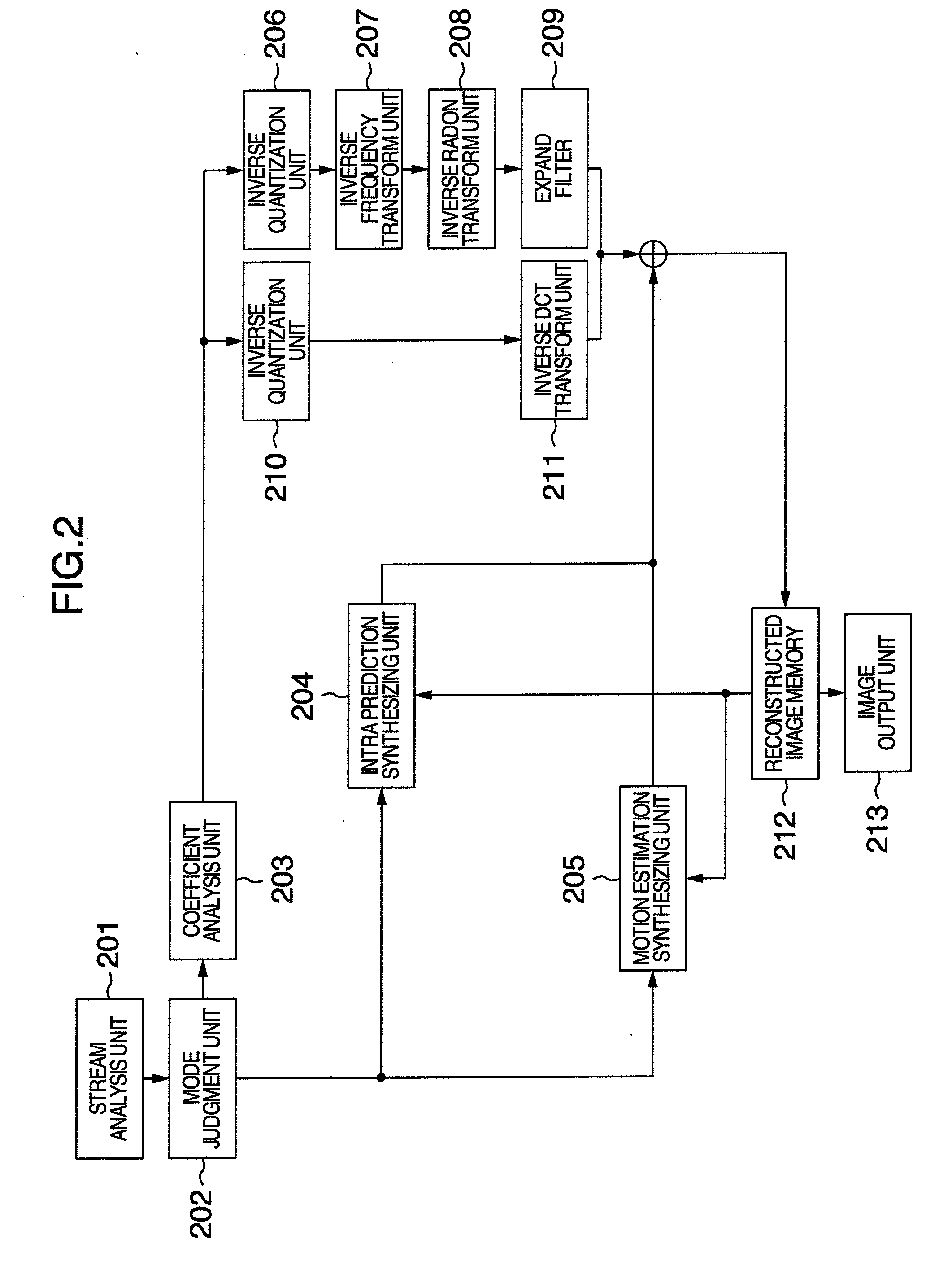
[0102]FIG. 2 shows a block diagram of an image decoding apparatus in a third embodiment of the invention.

[0103]The image decoding apparatus is constituted by a stream analysis unit 201, a mode judgment unit 202, a coefficient analysis unit 203, an intra prediction synthesizing unit 204, a motion estimation synthesizing unit 205, an inverse quantization unit 206, an inverse frequency transform unit 207, an inverse Radon transform unit 208, an expand filter 209, an inverse quantization unit 210, an inverse DCT transform unit 211, a reconstructed image memory 212, and an image output unit 213.

[0104]An operation of constitutional elements in the image decoding apparatus will be described below.

[0105]In addition, the operation of the respective construction elements in the image decoding apparatus may be a self-directive operation as described below, and may also be realized to cooperate with software stored in a control unit and memory unit, for example.

[0106]First, the stream analysis ...


PUM


Abstract

An image coding and decoding apparatus includes functions, in which an image of every block including either an entire input image or an image divided from the input image is compressed, a Radon transform is applied to the compressed image to generate a coefficient, the generated coefficient is transformed in a frequency, and the frequency transformed coefficient is quantized to generate coding data to generate a coding stream, in the encoding, and an inverse quantization is applied to a coding coefficient included in the coding stream to generate a coefficient, an inverse frequency transform is applied to the generated coefficient, an inverse Radon transform is applied to the inversed frequency transformed coefficient to generate a decompress image, an expand process is applied to the decompression image to decode a residual component, and a predicted image is synthesized with the residual component to generate a reconstructed image, in the decoding.

Description

[0001]The present application claims priority from Japanese application JP 2007-152242 filed on Jun. 8, 2007, the content of which is hereby incorporated by reference into this application.BACKGROUND OF THE INVENTION[0002]1. Field of the Invention[0003]The present invention relates to an image coding method and image coding apparatus for encoding an image, and an image decoding method and image decoding apparatus for decoding coded image data.[0004]2. Description of the Related Art[0005]A specification, H.264 / AVC (Advanced Video Coding), has been defined as a method of digitizing image and audio information to record and transmit it to another.[0006]In the H.264 / AVC system, a pattern having highest image quality for an amount of code can be selected from various predictive coding patterns, in the case of a coding unit for each frame called a macro block. Such a coded pattern is referred to as a coding mode. The foregoing system has been disclosed in “Joint Video Team (JVT) of ISO / IE...

Claims


Application Information

Patent Timeline
IPC IPC(8): H04N5/917H04N19/50H03M7/30H04N19/12H04N19/134H04N19/136H04N19/137H04N19/147H04N19/196H04N19/423H04N19/46H04N19/503H04N19/593H04N19/60H04N19/61H04N19/625H04N19/63H04N19/70H04N19/80H04N19/85H04N19/91
CPCH04N19/176H04N19/147H04N19/46H04N19/59H04N19/61H04N19/103H04N19/12H04N19/122
Inventor MURAKAMI, TOMOKAZUTAKAHASHI, MASASHI
Owner HITACHI LTD
Why Eureka
Try Eureka