Image forming apparatus and control program of image forming apparatus

a technology of image forming apparatus and control program, which is applied in the direction of electrographic process apparatus, printing, instruments, etc., can solve the problems of image quality change page by page, program capacity (memory capacity) to be increased, and the state of light source deterioration differs by each light source. achieve the effect of stabilizing the cleaning of the image carrier

Active Publication Date: 2008-12-11
KONICA MINOLTA BUSINESS TECH INC
View PDF5 Cites 4 Cited by
  • Summary
  • Abstract
  • Description
  • Claims
  • Application Information

AI Technical Summary

Benefits of technology

[0022]In the image forming apparatus reflecting still another aspect of the present invention, the laser beam emission onto outside of the image area is an emission for latent image formation to stabilize cleaning of the image carrier.

Problems solved by technology

However, in this case of decreasing the number of used light sources, the difference of light emitting period between the used light source and the unused light source is generated, and a problem results in that the state of light source deterioration differs by each of the light sources.
In JPA2002-166592, technology regarding beam switching is disclosed, however this causes a new problem in that the program capacity (memory capacity) must be increased due to the complicated control program.
In this case, it is necessary to control the switching of light sources page by page, and a new problem may be generated in that image quality changes page by page due to the switching of the light sources.
This image quality change may be a serious problem since this leads to a color shift in case of color image formation.

Method used


Image

  • Image forming apparatus and control program of image forming apparatus
  • Image forming apparatus and control program of image forming apparatus
  • Image forming apparatus and control program of image forming apparatus

Examples


first embodiment

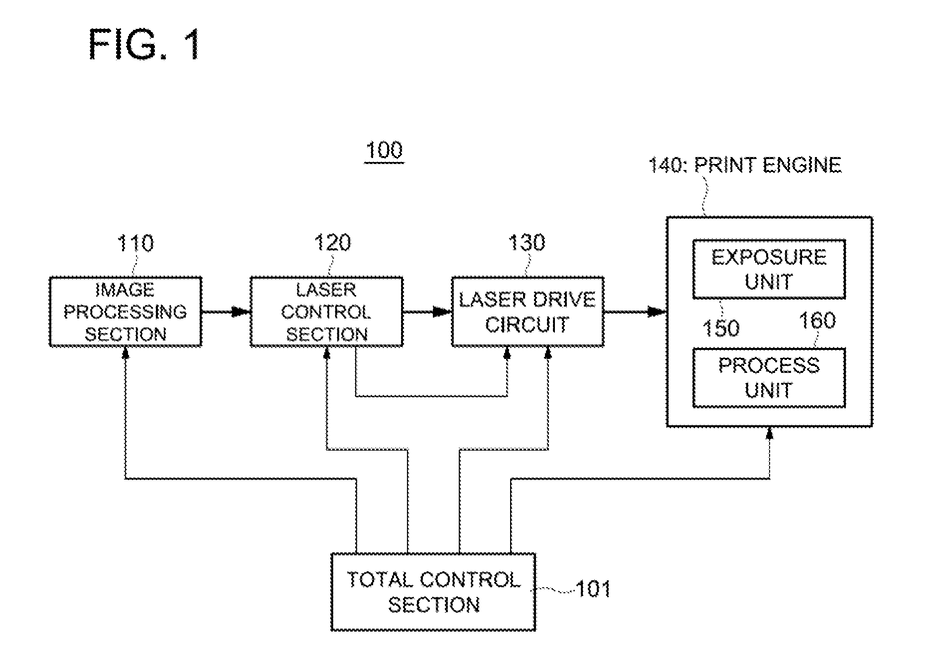
[0034]Sign 101 indicates a total control section configured with such as a CPU to control each part of image forming apparatus 100. Sign 110 indicates an image processing section to execute prescribed image processing onto image data. Sign 120 indicates a laser control section to regulate laser emission in accordance with the image data and prescribed command data. Sign 130 indicates a laser drive circuit to drive light sources based on the control of laser control section 120. Sign 140 indicates a print engine to form images by exposure, which includes exposure unit 150 to conduct scanning of multiple laser beams, and process unit 160.

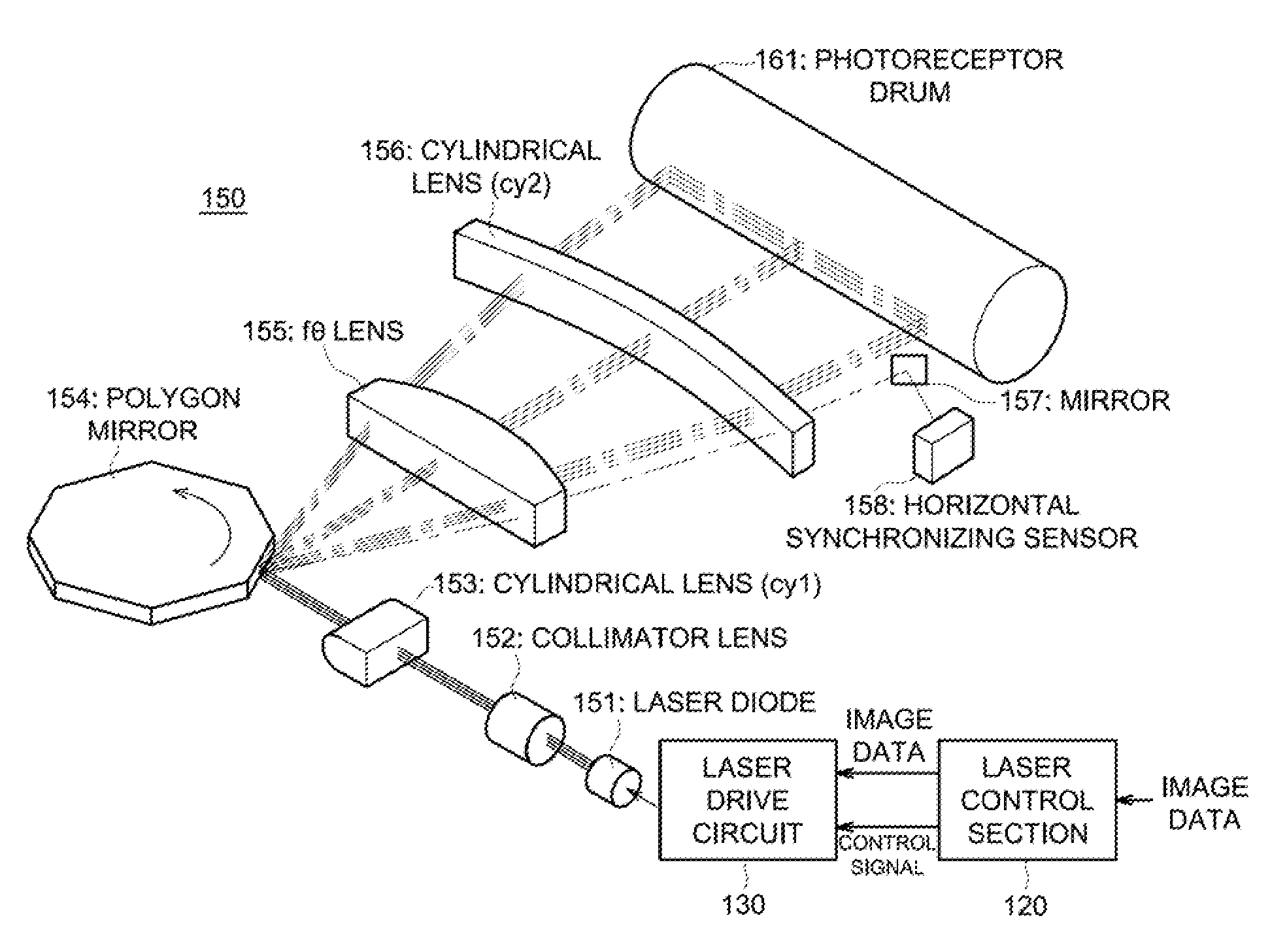
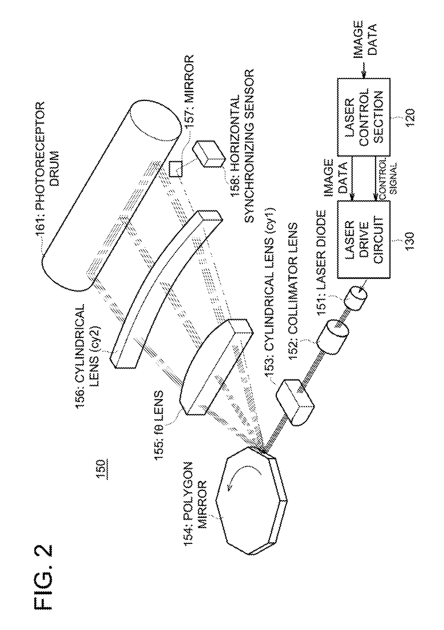
[0035]FIG. 2 schematically shows the parts of laser control section 120, laser drive circuit 130, and exposure unit 150 partially in perspective view. Further, the parts shown in perspective view in FIG. 2 are illustrated in FIG. 3 in a plan view.

[0036]In FIG. 2 and FIG. 3, exposure unit 150 comprises laser diode 151 as multiple light sources which ge...


PUM


Abstract

An image forming apparatus for simultaneously conducting multiple lines of exposure by scanning multiple laser beams from multiple light sources onto an image carrier in a main scanning direction, including: multiple light sources which are driven to emit laser beams based on image data; and a control section capable of controlling an image formation in two types of image forming modes of a first image forming mode where an image is formed at a first image forming speed by using all the multiple light sources, and a second image forming mode where the image is formed without using at least one of the multiple light sources at a second image forming speed slower than the first image forming speed,
wherein the control section controls a light source which is not used in the second image forming mode to emit a laser beam onto outside of an image area.

Description

CROSS REFERENCE TO RELATED APPLICATION[0001]The present application is based on Japanese Patent Application No. 2007-153043 filed with Japanese Patent Office on Jun. 8, 2007, the entire content of which is hereby incorporated by reference.BACKGROUND OF THE INVENTION[0002]1. Field of the Invention[0003]The present invention relates to an image forming apparatus such as a copier and a program of the image forming apparatus, and particularly to an image forming apparatus having a function to write an image of multiple scanning lines in a single scanning process onto a recording medium such as a photoreceptor by utilizing laser beams from multiple light sources, and a control program thereof.[0004]2. Description of the Related Art[0005]An image forming apparatus is known which forms one line image in a main scanning direction based on image data, and forms one page of image by repeating the image formation of the main scanning direction line by line in a sub-scanning direction.[0006]As ...

Claims


Application Information

Patent Timeline
Patent Type & Authority Applications(United States)
IPC IPC(8): G03G15/043
CPCH04N1/1135H04N1/1911
Inventor SEKINE, HARUYUKI
Owner KONICA MINOLTA BUSINESS TECH INC
Why Eureka
Try Eureka