Cryogenic liquid tank and method

a cryogenic liquid tank and liquid tank technology, applied in the direction of container discharging methods, vessel construction details, transportation and packaging, etc., can solve the problems of high cost, high cost, and high cost of cryogenic liquid tanks, and achieve the effect of inhibiting heat leakag

Inactive Publication Date: 2008-12-18
PRAXAIR TECH INC
View PDF20 Cites 27 Cited by
  • Summary
  • Abstract
  • Description
  • Claims
  • Application Information

AI Technical Summary

Benefits of technology

[0007]The present invention in one aspect provides a tank for containing a cryogenic liquid. In accordance with the invention an inner vessel is provided for containing the cryogenic liquid and an outer vessel, surrounding the inner vessel, defines an insulation space there between and an insulation material is located within the insulation space to inhibit heat leakage from the ambient into the inner vessel.

Problems solved by technology

When the vacuum level becomes compromised, the insulation materials lose their insulation performance very quickly.
Any mechanical damage to the tank vessel or connecting pipes will cause loss of vacuum in the insulation space.
This occurrence of vacuum loss is common in cryogenic tanks that are mounted on road trailers in regions where there are poor roads.
Typically, cryogenic road tankers require about one to two repairs per year and each repair can take up to several weeks or even months to perform.
However, in any tank used in storing a cryogenic liquid, whether containing a vacuum insulation, fiberglass or an aerogel, when moisture enters the insulation space, water will collect and freeze.
The use of purge gases as described in this patent could not be readily used in connection with cryogenic storage tanks that are more susceptible to damage either at the inner vessel or outer vessel due to the fact that damage to the inner vessel will cause leakage of pressurized cryogenic vapor into the insulation space to eventually damage the outer vessel.
Damage to the outer vessel will of course cause loss of the purge gas in the first instance.

Method used


Image

  • Cryogenic liquid tank and method
  • Cryogenic liquid tank and method
  • Cryogenic liquid tank and method

Examples


Embodiment Construction

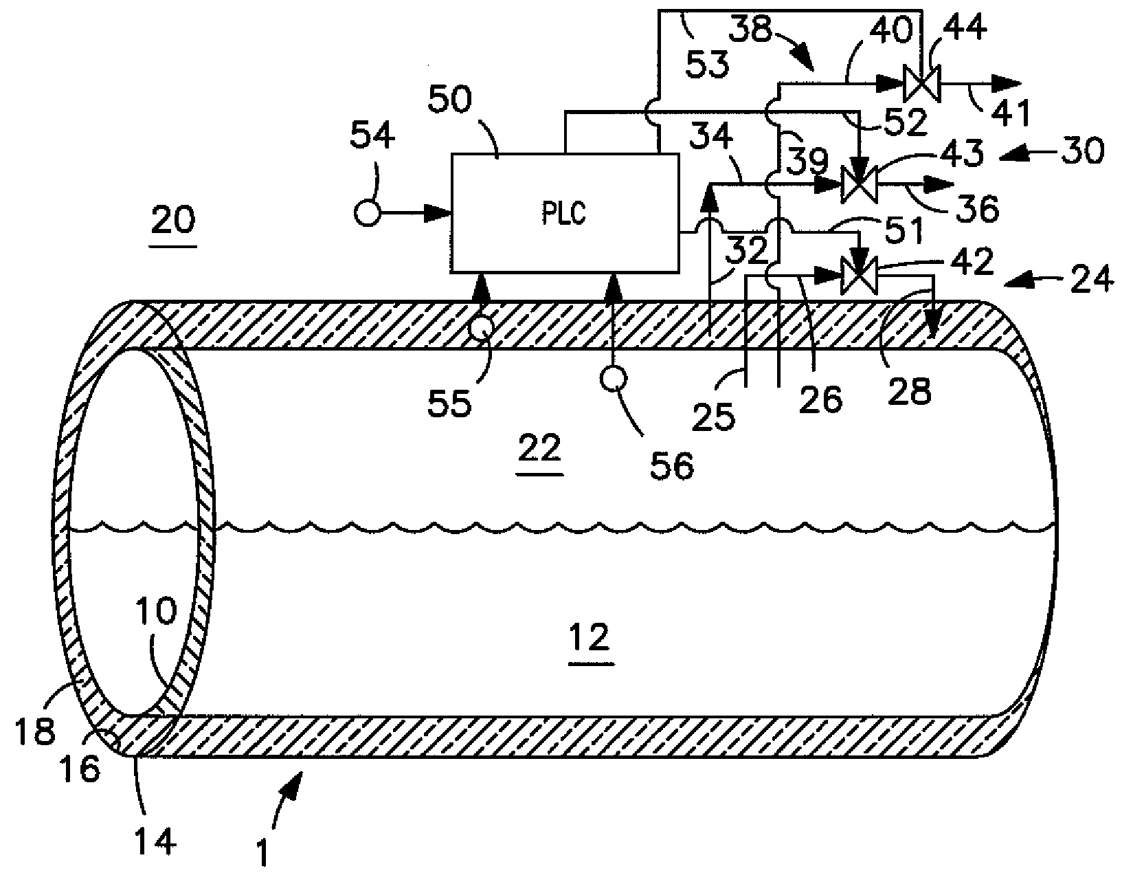
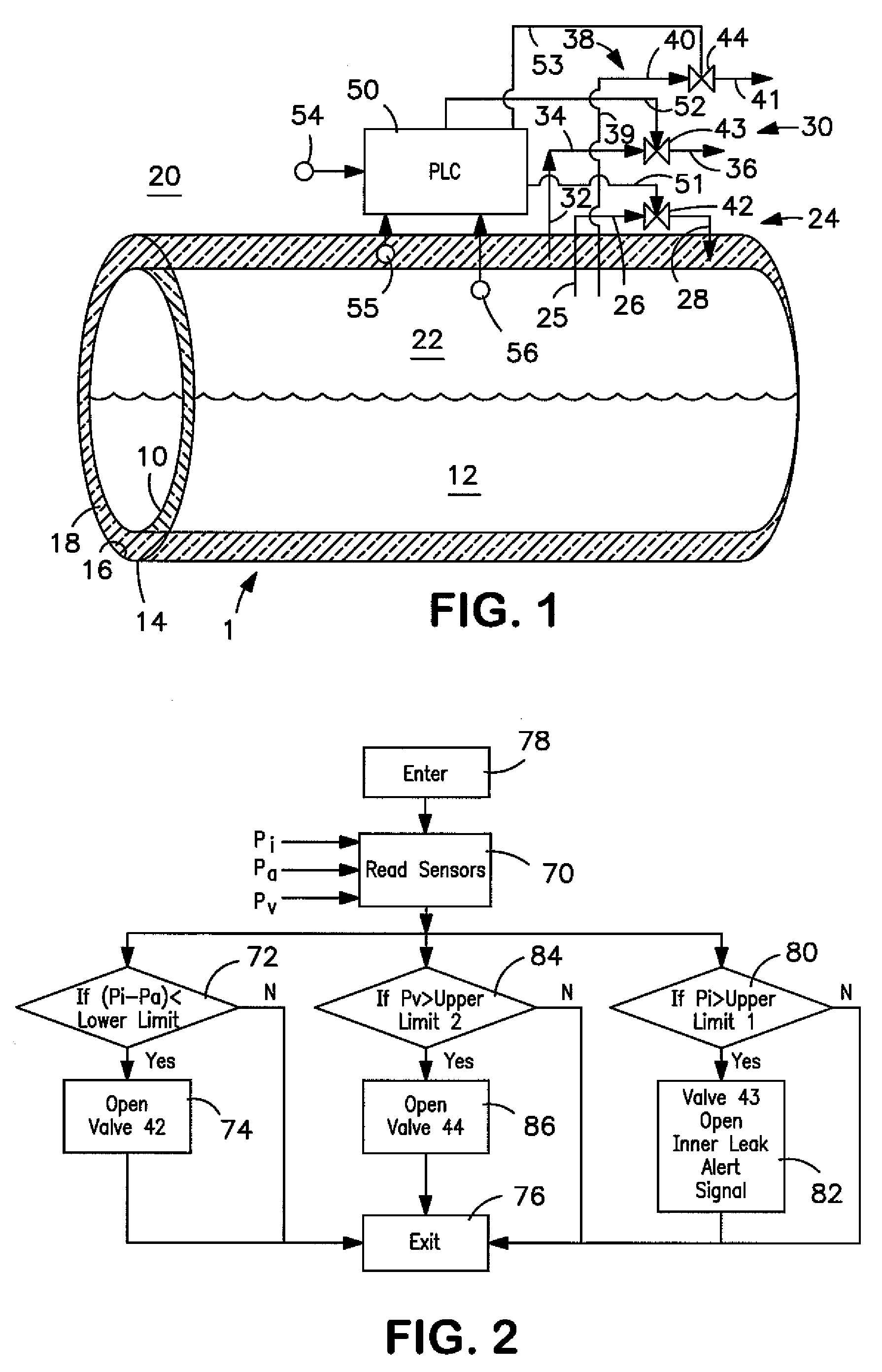
[0024]With reference to FIG. 1, a tank 1 in accordance with the present invention is illustrated. Tank 1 has a conventional inner vessel 10 for containing a cryogenic liquid 12. An outer vessel 14 surrounds the inner vessel to define an insulation space 16 between inner vessel 10 and outer vessel 12. Located within insulation space 16 is an aerogel insulation material 18 to inhibit heat leakage from ambient 20 into inner vessel 10.

[0025]Invariable heat leakage into inner vessel 10 vaporizes cryogenic liquid 12 that collects in an ullage space of inner vessel 10 as cryogenic vapor 22. In order to prevent moisture from entering insulation space 16 a passageway 24 having sections 25, 26 and 28 is provided to introduce the cryogenic vapor 22 as a purge gas into insulation space 16. It is understood, however, that as an alternative, many tank systems and virtually all road trailers are provided with pressure building circuits in which cryogenic liquid is vaporized and introduced back int...


PUM


Abstract

A tank and method for containing a cryogenic liquid in which a purge gas is introduced into an insulation space defined between an outer vessel and an inner vessel to contain insulation material. The inner vessel is used to contain the cryogenic liquid. The purge gas can be cryogenic vapor evolved from the liquid and routed into the insulation space. Control of the purge gas within the insulation space can be provided by a programmable logic controller in which purge gas is vented from the insulation space should the pressure be indicative of a leak within the inner vessel and purge gas is introduced into the insulation space should the pressure be below the ambient to maintain a positive purge gas pressure. An adsorbent bed can also be located within the insulation space to adsorb any moisture.

Description

FIELD OF THE INVENTION[0001]The present invention relates to a tank and method for containing a cryogenic liquid that is designed to allow a purge gas to be introduced into an insulation space to prevent moisture from collecting within the insulation space and degrading insulation performance.BACKGROUND[0002]Cryogenic road and storage tanks are typically vacuum insulated. These tanks are formed with inner and outer vessels and an insulation space defined between the inner and outer vessels that contains insulation to prevent heat leakage from the ambient that would otherwise cause product vaporization and therefore, product loss. The commonly used insulation materials include fiberglass, PEARLITE and super insulation. The performance of these insulation systems depend on the degree to which vacuum can be maintained within the insulation space. When the vacuum level becomes compromised, the insulation materials lose their insulation performance very quickly.[0003]Current cryogenic ta...

Claims


Application Information

Patent Timeline
Patent Type & Authority Applications(United States)
IPC IPC(8): F17C13/02F17C3/02
CPCF17C3/02F17C13/02Y02E60/321F17C2201/0104F17C2201/035F17C2203/012F17C2203/0325F17C2203/0341F17C2203/0345F17C2203/0387F17C2203/0391F17C2203/0629F17C2205/018F17C2205/0326F17C2205/0332F17C2221/011F17C2221/013F17C2221/014F17C2221/016F17C2223/0161F17C2223/033F17C2223/043F17C2250/032F17C2250/036F17C2250/043F17C2250/0486F17C2260/033F17C2270/0171Y02E60/32
Inventor LUO, YANGMARQUES, REINALDOCHAO, CHIEN-CHUNG
Owner PRAXAIR TECH INC
Why Eureka
Try Eureka