
Cold launch system comprising shape-memory alloy actuator

a technology of shape memory and actuator, which is applied in the direction of spring guns, white arms/cold weapons, weapons, etc., can solve the problems of increasing the weight of the missile, increasing the cost and complexity of the launch system, and creating a residual thermal signatur

Inactive Publication Date: 2008-12-18
LOCKHEED MARTIN CORP
View PDF33 Cites 2 Cited by
  • Summary
  • Abstract
  • Description
  • Claims
  • Application Information

AI Technical Summary

Benefits of technology

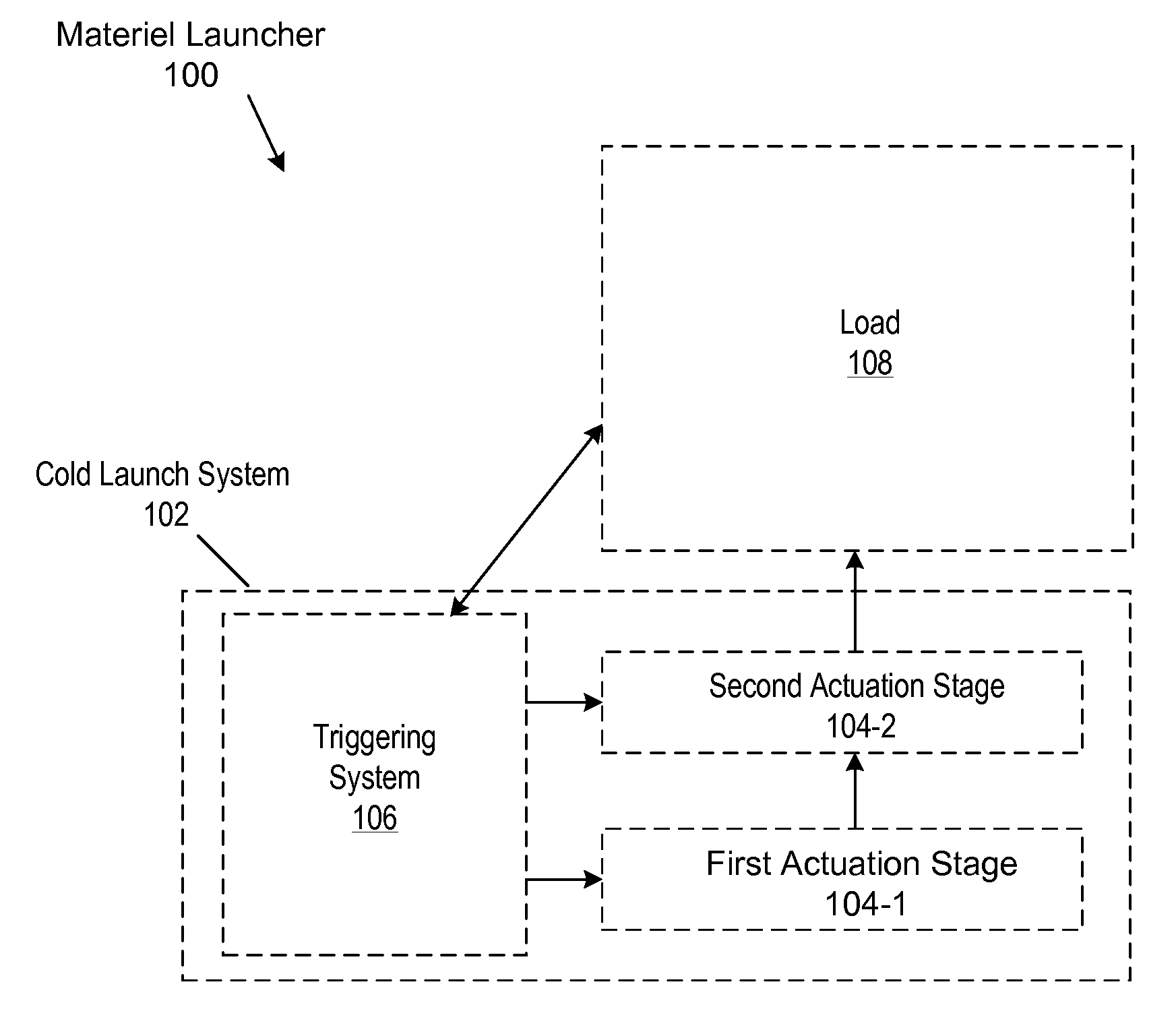
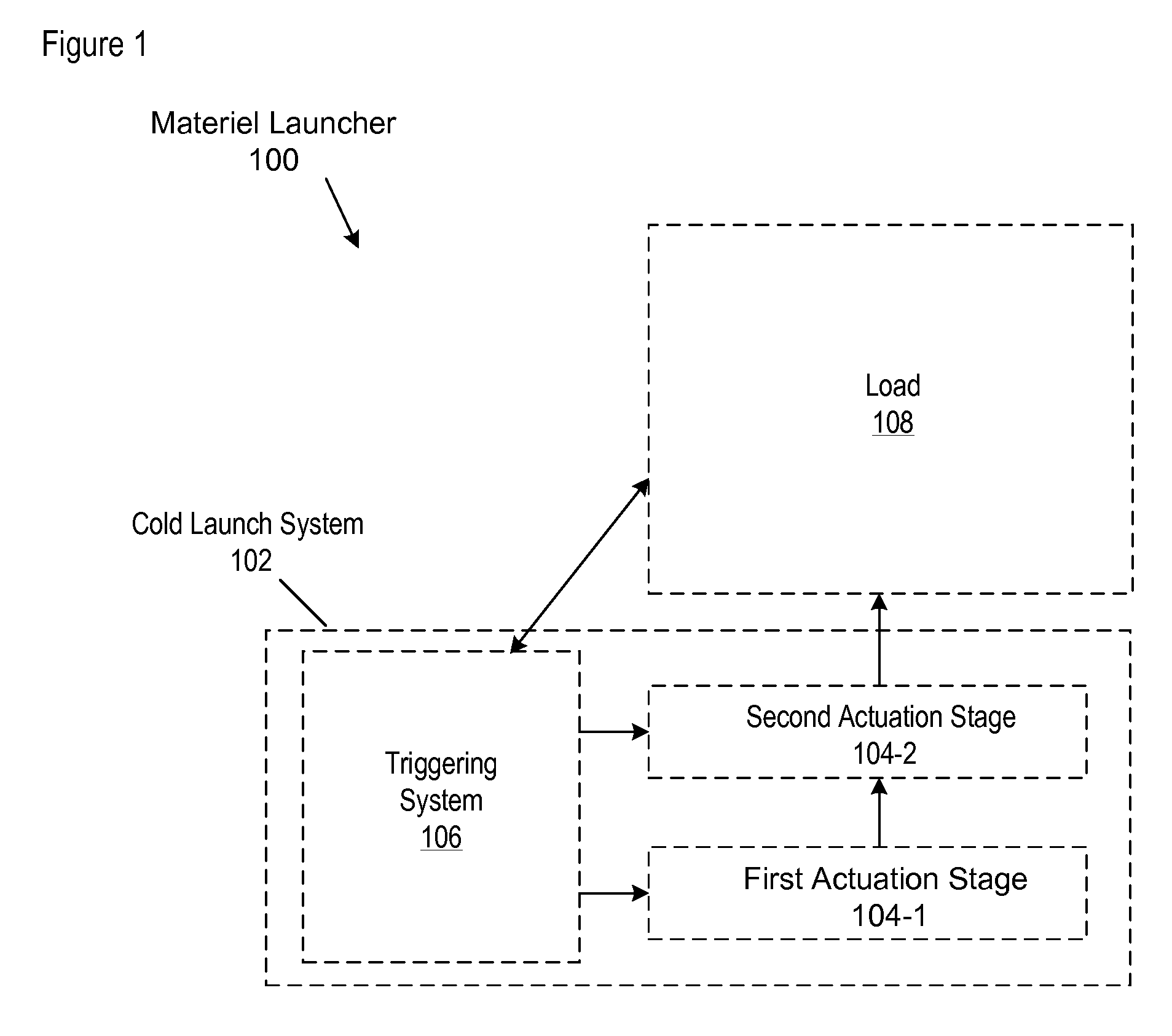
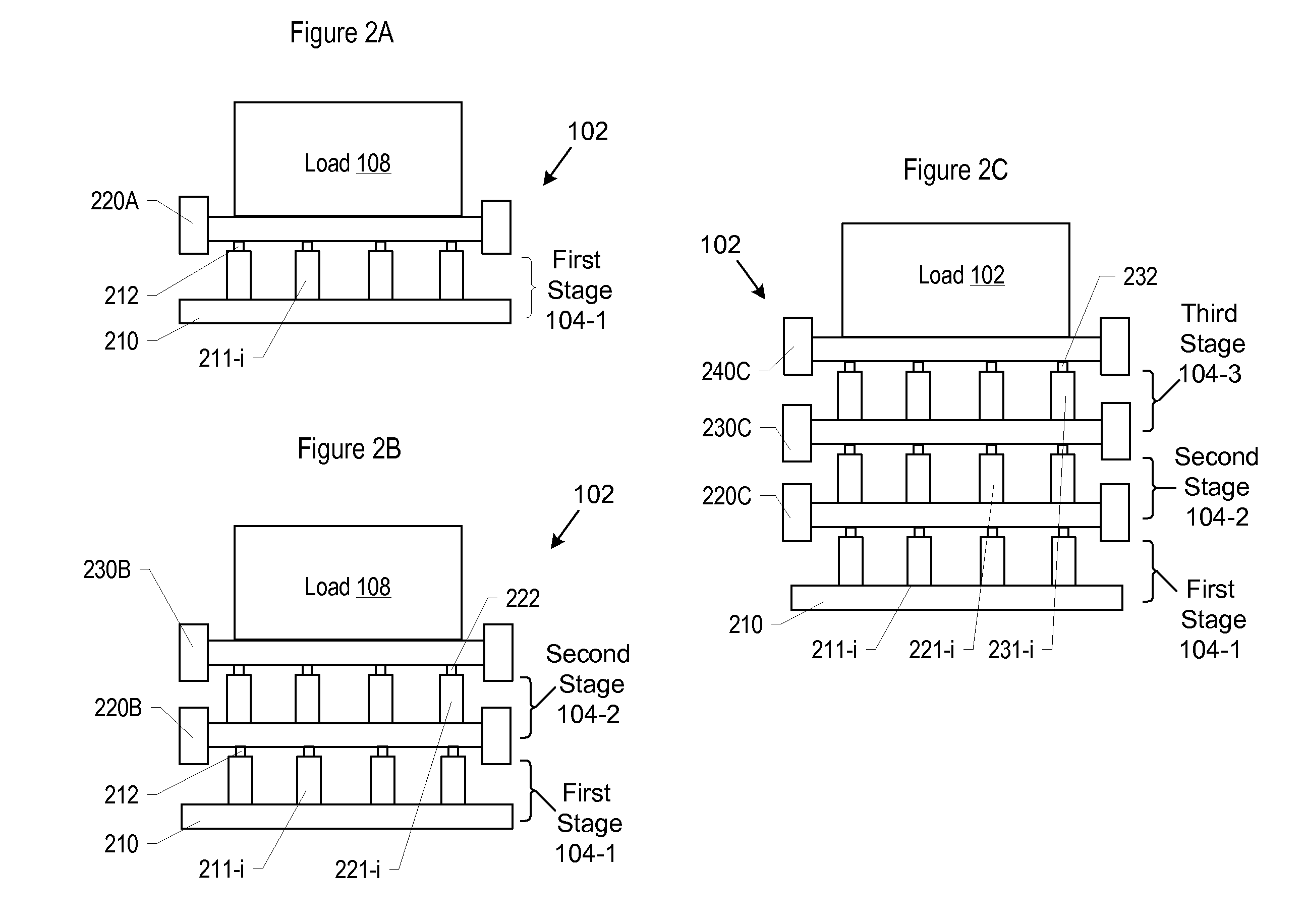
The present invention provides a cold-launch system that uses shape-memory-alloy actuators to accelerate a load to a required velocity. This system is cost-effective and overcomes the shortcomings of previous systems. The actuators are triggered simultaneously, resulting in a high launch velocity. The system can have multiple stages of actuators that sequentially trigger, increasing the velocity of the load. The platforms that support the actuators are one-way, meaning they can only move in the direction of launch. This prevents the platforms from locking in position and decreasing the force that is released. The cold-launch system is efficient and effective for use in outer space and can be used in terrestrial applications as well.

Problems solved by technology

Direct exposure to the plume would have an adverse effect on the missile, the missile canister, other launch structures, and the surrounding environs (e.g., deck of a ship, etc.).
Incorporation of the exhaust-gas management system and the protective materials necessarily enlarges the missile-launch system as well as increasing its weight, cost and complexity.
Furthermore, the heating of the launch structure and deck that results from hot launch creates a residual thermal signature.
This signature is readily detectable by various sensors, and therefore potentially compromises the survivability of the missile launcher and, indeed, the ship or vehicle that supports it.
Also, by its nature, hot launch technology increases the volatility of a missile due to the presence of the additional energetics, which are stored in the missile's booster.
But existing cold launch systems are not without drawbacks of their own.
One drawback is that most cold launch system include a substantial number of additional components, which raises reliability issues.
Another drawback is that in some cold launch systems, the missile is exposed to high-pressure gas from a gas generator (that provides the pressure for launch).
Also, electromagnetic launch systems require a great deal of electrical current to launch a missile.

Method used


Image

  • Cold launch system comprising shape-memory alloy actuator
  • Cold launch system comprising shape-memory alloy actuator
  • Cold launch system comprising shape-memory alloy actuator

Examples


Embodiment Construction

[0040]The following terms are defined for use in this Specification, including the appended claims:[0041]Physically-coupled means direct, physical contact between two objects (e.g., two surfaces that abut one another, etc.).[0042]Mechanically-coupled means that two or more objects interact with one another such that movement of one of the objects affects the other object. For example, consider an actuator and a platform. When triggered, the actuator causes the platform to move. The actuator and the platform are therefore considered to be “mechanically-coupled.” Mechanically-coupled devices can be, but are not necessarily, physically coupled. In particular, two devices that interact with each other through an intermediate medium are considered to be mechanically coupled. Continuing with the example of the platform and the actuator, if the platform supports a load such that the load moves when the platform moves (due to the actuator), then the actuator and the load are considered to b...


PUM


Abstract

A cold-launch uses shape-memory-alloy (“SMA”) actuators to accelerate materiel to a required launch velocity. The SMA actuators are arranged into one or more actuation stages. SMA actuators within a given actuation stage are simultaneously triggered. Actuation stages, however, are triggered sequentially, each triggering adding to the velocity of the materiel.

Description

FIELD OF THE INVENTION[0001]The present invention relates generally to launch systems, and more particularly to cold launch systems.BACKGROUND OF THE INVENTION[0002]A canisterized missile is typically launched using the missile's launch booster—so called “hot launch.” When the booster fires, a plume of very high-temperature, high-velocity exhaust gas is generated. The plume, which in some cases contains metallic particulates, is very erosive. Direct exposure to the plume would have an adverse effect on the missile, the missile canister, other launch structures, and the surrounding environs (e.g., deck of a ship, etc.).[0003]As a consequence, most missile-launch systems include an exhaust-gas management system, which directs the booster plume away from the missile and launch structure. To withstand the plume's extreme conditions, the launch structure, as well as the exhaust-gas management system itself, must incorporate thermal-protection and erosion-protection materials.[0004]Incorp...

Claims


Application Information

Patent Timeline
Patent Type & Authority Applications(United States)
IPC IPC(8): F41F1/00
CPCF41B7/00F41F1/00F41F3/04
Inventor SHAH, TUSHAR K.CORBOY, GRANT W.KRAFT, II, WILLIAM RUSSELL
Owner LOCKHEED MARTIN CORP
Learn More