Cleaning Process for Cleaning Filtration Material of a Gas Filter and a Device for Carrying Out the Process

a technology of filtration material and cleaning process, which is applied in the direction of filtration separation, auxillary pretreatment, separation process, etc., can solve the problems of ineffective methods, high cost and complexity of filter system design, so as to reduce the risk of gas flow and increase the life of filtration material , the effect of high efficiency of rfp technology

Inactive Publication Date: 2008-12-18
ZIMMER SEBASTIAN
View PDF14 Cites 4 Cited by
  • Summary
  • Abstract
  • Description
  • Claims
  • Application Information

AI Technical Summary

Benefits of technology

[0012]Stated clearly, the invention is directed to a process for removing the separated particles from the filtration material by means of a four step cleaning procedure. Step one hinders the gas flow from passing through the filtration material by closing a single segment or a row of filter segments. Step two provides a slow gas flow to the separated filter segments to cause a reverse gas flow through the filtration material. Step three opens an impulse valve (e.g. diaphragm valve) for an ultra short time to create a compressed gas impulse for disengaging the particles which did not fall off the filtration material during step two of the cleaning process. Step four shuts off the reverse flow gas supply.
[0013]The advantage of this invention is that the filtration material is pre-cleaned in step two of the cleaning process by applying cheap low pressure cleaning gas. The slow reverse flow through the filtration material avoids blasting of the filter-cake (agglomerated particles adhering to the filtration material) and cleans the filtration material in a gentle manner. Step three provides final cleaning by the compressed gas impulse which shakes or blows off the rest of the filtered particles and is supported by the reverse flow gas. The invention combines the “reverse flow cleaning method” with the “pulse jet cleaning method” to achieve final and complete cleaning of the filtration material.
[0014]Due to the high efficiency of the “RfP”-technology, the filter area in comparison with the reverse flow system or pulse jet system can be reduced by 10% to 25%, the pressure of compressed gas and its consumption can be reduced by 20% to 50% or the filter pressure drop can be reduced up to 50%. The lifetime of the filtration material is increased by at least 200%. The technology provides highest operation safety even under changing operation and dust conditions. Moreover, the technology is simple and cheap.

Problems solved by technology

This technology requires an expensive and complex design of the filter system (e.g. big dampers for raw gas and clean gas) and requires more filtration material (for an increased filtration surface).
Finally, the method is not very effective and provides only low operation safety (capability to cover changing filtration conditions).
The gas impulse used must be so strong that the filtered particles overcome the adherence to the filtration material caused by the gas stream still flowing through the filtration material; the efficiency of the vibration is not guaranteed.
The disadvantages of this technology are, (1) that a huge amount of compressed cleaning gas is required, (2) that the shock waves cause a strong stress on the filtration material, which reduces the life time of the material, and (3) that—caused by the gas flow still flowing through the filtration material—the filtered particles are massaged into the filtration material, which increases the pressure drop of the filtration material up to 20 times. A further disadvantage is that cleaning with a filter-cake blast causes a stream of fine particles which return to the cleaned filter segment or to the one next to it.
The aforementioned disadvantages reduce the efficiency of the technology and demand a low gas to filtration material ratio (that is: amount of gas flow per unit of time and per square metre).

Method used


Image

  • Cleaning Process for Cleaning Filtration Material of a Gas Filter and a Device for Carrying Out the Process
  • Cleaning Process for Cleaning Filtration Material of a Gas Filter and a Device for Carrying Out the Process
  • Cleaning Process for Cleaning Filtration Material of a Gas Filter and a Device for Carrying Out the Process

Examples


Embodiment Construction

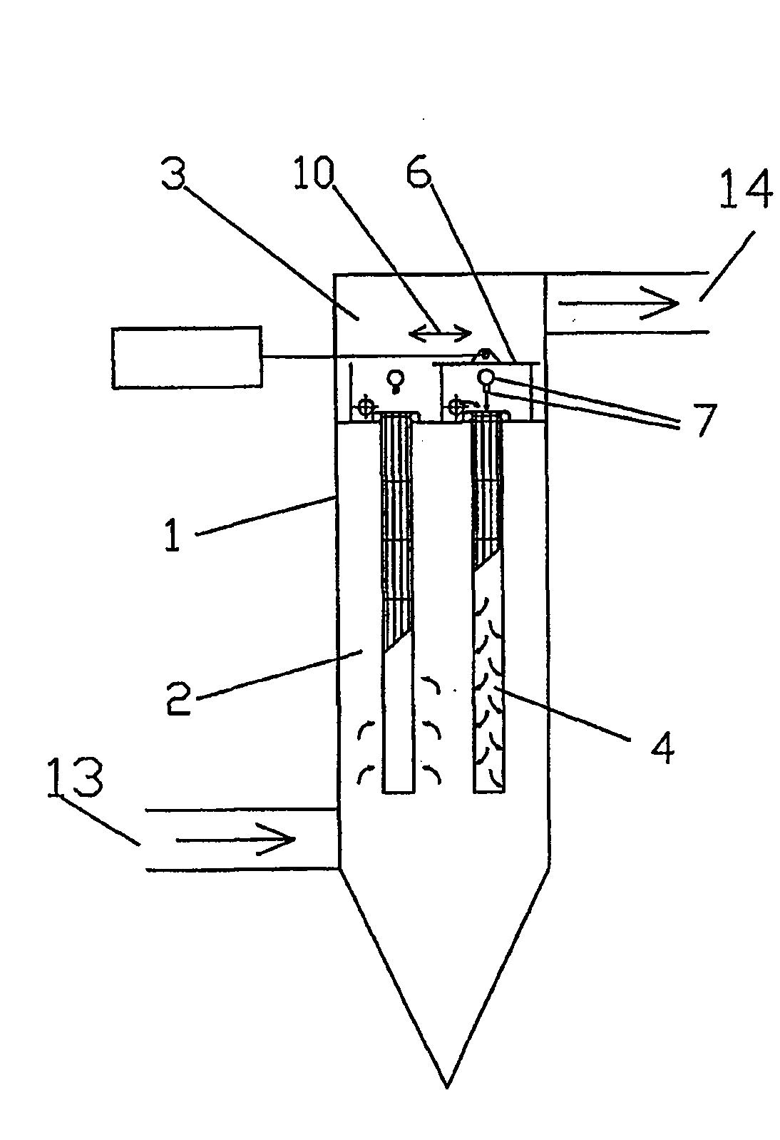
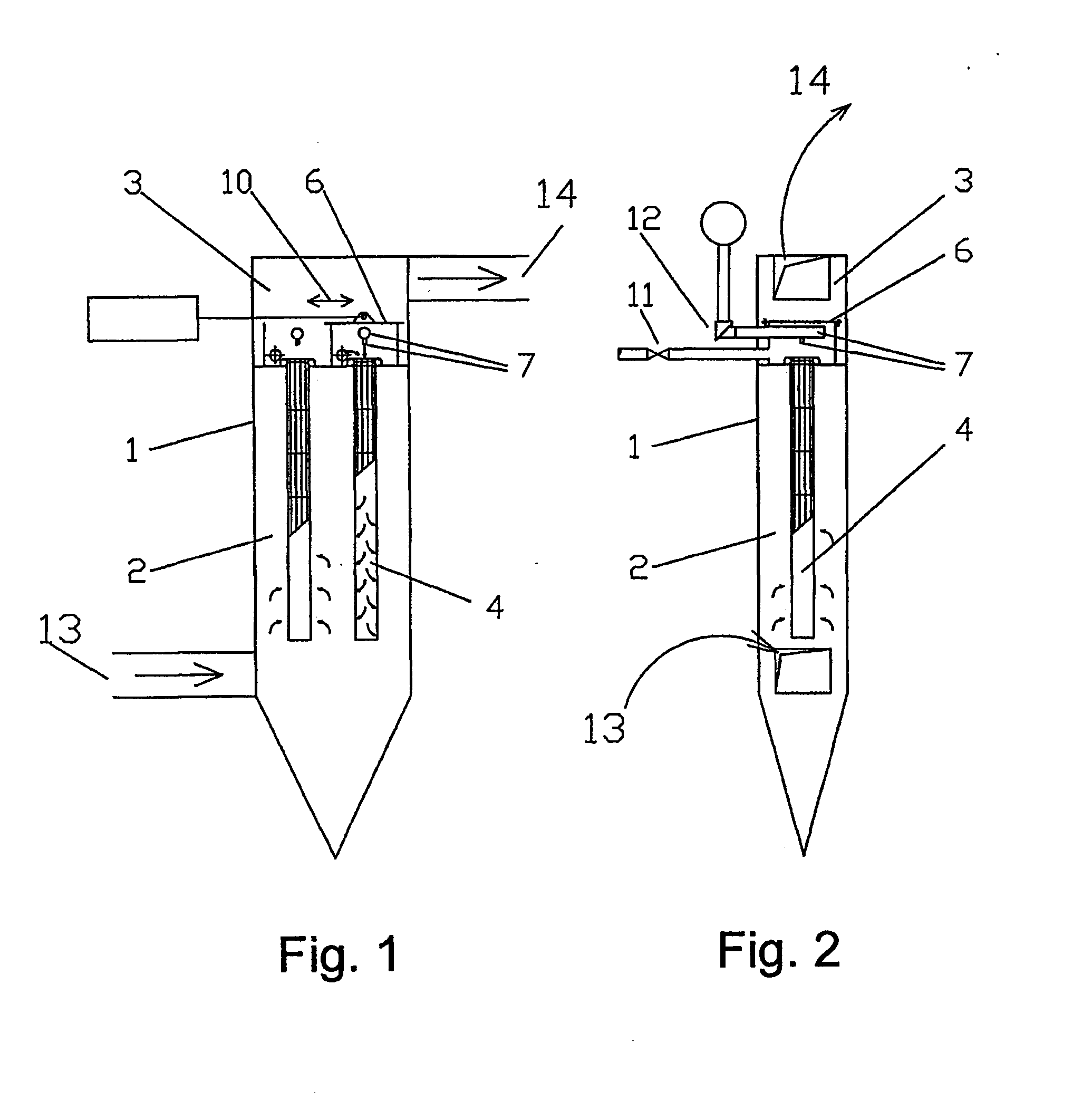
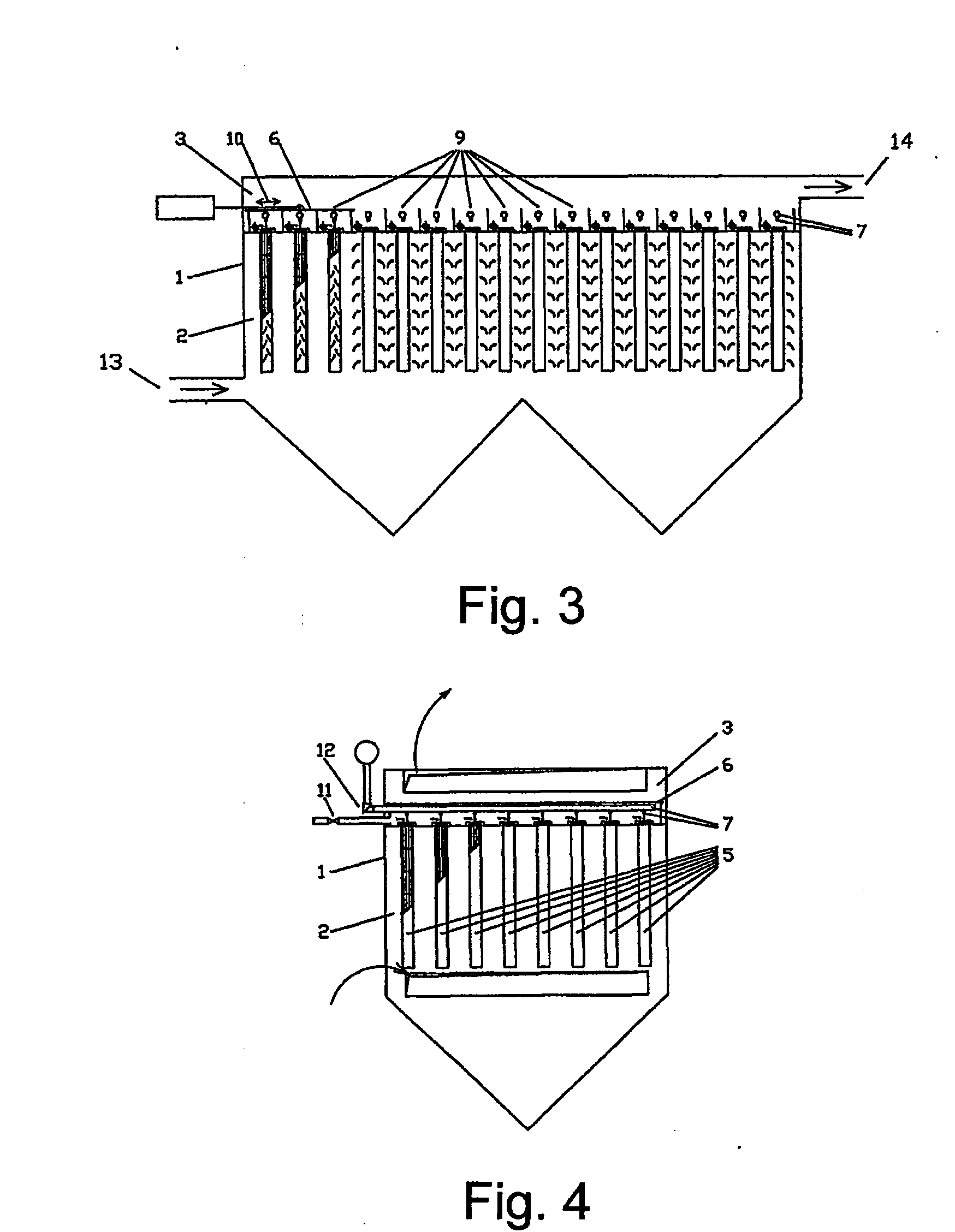
[0024]The invention is suitable for all cleaning systems for gas filter filtration material. The following describes the “RfP”-technology according to examples of a fabric filter filtration material cleaning system (FIGS. 1-4) and of a membrane filter filtration material cleaning system (FIGS. 5, 6).

[0025]The filter filtration material cleaning system shown in each figure contains a casing (1) with a particle-laden gas side (2) and a clean gas side (3). A single filter segment (4) or a row of filter segments (5) can be separated from the normal gas stream by a slide plate (6), which is located next to a filter segment, covering the nozzle pipe (7) or being connected to the nozzle pipe (8). The slide plate (6) can also cover several filter segment rows (9) (see FIG. 4).

[0026]In step one of the cleaning procedure, the slide plate (6) opens one filter segment, a row or several rows of filter segments, which reduces the filter filtration material pressure loss immediately, and slowly cl...


PUM

PropertyMeasurementUnit
timeaaaaaaaaaa
pressure dropaaaaaaaaaa
speedaaaaaaaaaa

Abstract

A cleaning process for filtration material of a gas filter is disclosed. A first step hinders the gas flow from passing through the filtration material by closing the clean gas side of a single segment or a row of filter segments. A second step provides a slow gas flow to the closed filter segments to cause a reverse gas flow through the filtration material. A third step opens an impulse valve for an ultra short time to create a compressed gas impulse for disengaging the particles which did not fall off the filtration material during the second step of the cleaning process. A fourth step shuts off the reverse flow gas supply. A device for separating one or several filter segments from the clean gas side of the filter filtration material is also disclosed.

Description

FIELD OF THE INVENTION[0001]The invention is related to a cleaning process for cleaning filtration material of a gas filter which is used to clean filter filtration material of any shape, material and size arranged in a single filter segment or in filter segment sets, whereby particle-laden gas flows to the filtration material, being for instance a fabric or another porous material, while the particles are held back by the filtration material and the clean or almost clean gas passes through. The invention also describes a method and a device for separating a single or several filter segments from the filtration material clean gas side or particle-laden gas side.BACKGROUND INFORMATION[0002]Conventional filter filtration material technologies (especially for fabric filter) operate as reverse flow cleaning systems or as online pulse jet cleaning systems. The reverse flow technology is rather old while the pulse jet technology is presently the most common.[0003]The reverse flow technolo...

Claims


Application Information

Patent Timeline
Patent Type & Authority Applications(United States)
IPC IPC(8): B01D46/46B01D46/00
CPCB01D46/002B01D46/0058B01D46/0067B01D46/0068B01D46/04B01D46/90B01D46/58B01D46/70B01D46/71
Inventor ZIMMER, SEBASTIAN
Owner ZIMMER SEBASTIAN
Why Eureka
Try Eureka