Filter Medium, Process for Producing the Same, Method of Use Thereof, and Filter Unit

Inactive Publication Date: 2008-12-18
NITTO DENKO CORP
View PDF29 Cites 43 Cited by
  • Summary
  • Abstract
  • Description
  • Claims
  • Application Information

AI Technical Summary

Benefits of technology

[0011]According to the present invention, the filter medium including a web layer made of polymeric fibers and formed by electrospinning enables reducing an i

Problems solved by technology

Such glass fiber filter media, however, include minute fibers attached thereto and bending them while processing causes self-dusting, and thus the filter media may contaminate the clean room or inside of the turbine with the glass fibers.
For these reasons, long-term use of the PTFE filter media is difficult in an environment full of dus

Method used


Image

  • Filter Medium, Process for Producing the Same, Method of Use Thereof, and Filter Unit
  • Filter Medium, Process for Producing the Same, Method of Use Thereof, and Filter Unit
  • Filter Medium, Process for Producing the Same, Method of Use Thereof, and Filter Unit

Examples


example 1

[0051]A method of fabricating each sample of filter medium used for Example 1 is described below.

Sample 1

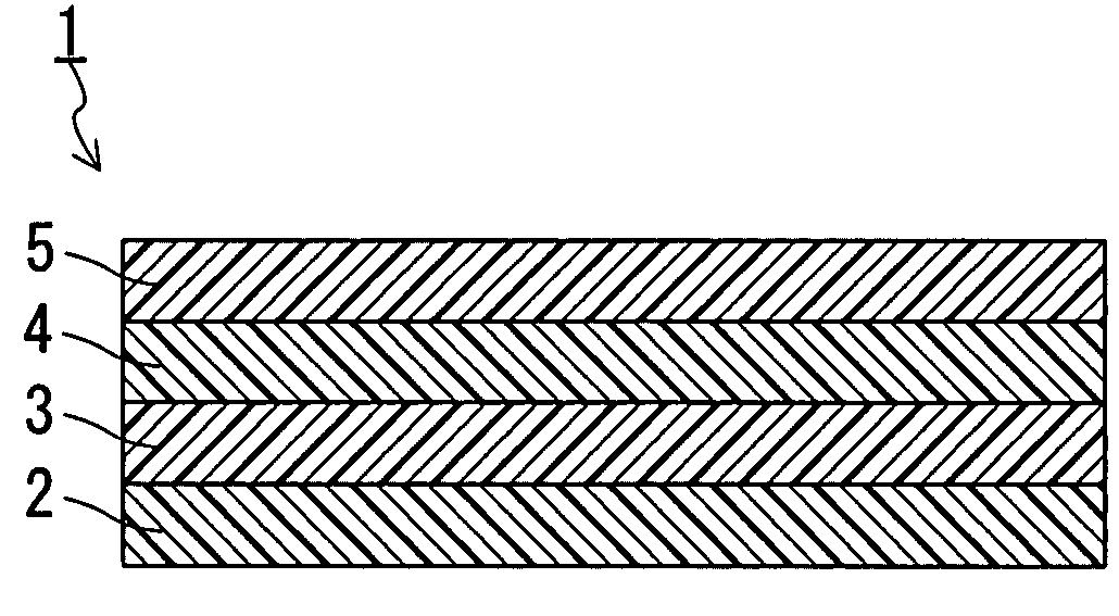
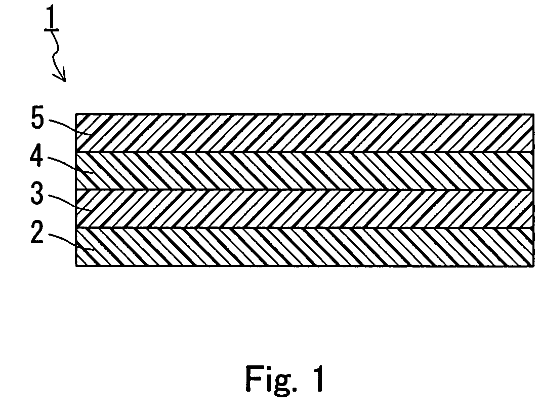
[0052]A PTFE paste was formed by uniformly mixing 100 parts by weight of PTFE fine powder and 30 parts by weight of liquid paraffin as a liquid lubricant. Next, the PTFE paste thus formed was preformed and then extrusion molded in a round bar shape, followed by rolling with a pair of metal rollers to form a PTFE film with a thickness of 0.2 m. Then, the liquid lubricant contained in the PTFE film thus formed was removed by extraction using normal decane and then the film was stretched 10 times in the longitudinal direction (lengthwise) and 30 times in the transverse direction (widthwise) to obtain a porous PTFE membrane (thickness of 10 μm, porosity of 93%, average pore size of 1.0 μm, average fiber diameter of 0.2 μm, pressure drop of 150.5 Pa, collection efficiency of 99.999%). The average fiber diameters, the pressure drop and the collection efficiency were measured by the met...

example 2

[0060]A method of fabricating each sample of filter medium used in Example 2 is described below.

Sample 2

[0061]A PTFE paste was formed by uniformly mixing 100 parts by weight of PTFE fine powder and 30 parts by weight of liquid paraffin as a liquid lubricant. Next, the PTFE paste thus formed was preformed and then extrusion molded in a round bar shape, followed by rolling with a pair of metal rollers to form a PTFE film with a thickness of 0.2 μm. Then, the liquid lubricant contained in the PTFE film thus formed was removed by extraction using normal decane and then the film was stretched 20 times in the longitudinal direction (lengthwise) and 30 times in the transverse direction (widthwise) to obtain a porous PTFE membrane (thickness of 15 μm, average fiber diameter of 0.02 μm, pressure drop of 125 Pa, collection efficiency of 99.98%). The average fiber diameters, the pressure drop and the collection efficiency were measured by the methods described above. The film was subjected to ...


PUM

PropertyMeasurementUnit
Diameteraaaaaaaaaa
Diameteraaaaaaaaaa
Diameteraaaaaaaaaa

Abstract

The present invention provides a filter medium reducing an increase in pressure drop while in use even in an environment where ultrafine particles form a large proportion of the particles to be collected. The filter medium includes a porous polytetrafluoroethylene (PTFE) membrane, an air-permeable supporting member and a web layer made of polymeric fibers formed by electrospinning (charge induction spinning, electrostatic spinning). The filter medium of the present invention may include an air-permeable adhesive layer adjacent to the web layer.

Description

TECHNICAL FIELD[0001]The present invention relates to a filter medium including a porous polytetrafluoroethylene membrane, a method of manufacturing the same and a method of using the same. The present invention also relates to a filter unit including the filter medium.BACKGROUND ART[0002]Conventionally, high efficiency filter media used for ventilation of a clean room or intake air for a turbine often employ paper-like filter media made of glass fibers with an added binder. Such glass fiber filter media, however, include minute fibers attached thereto and bending them while processing causes self-dusting, and thus the filter media may contaminate the clean room or inside of the turbine with the glass fibers.[0003]For this reason, much attention was drawn in recent years to filter media including a porous polytetrafluoroethylene (PTFE) membrane (PTFE filter media) as described in JP2000-61280 A (Reference 1), for example. The filter media described in JP2000-61280 A includes a porou...

Claims


Application Information

Patent Timeline
IPC IPC(8): B01D39/16B01D50/00B05D5/10D04H1/42
CPCB01D39/1623B01D2239/0478B01D2239/0631B01D2239/065B01D2239/083B01D2239/10B01D2239/1233D01D5/0038D01F6/18D04H1/42D04H13/00D04H1/4282D04H1/4326D04H1/43828D04H1/43838B01D39/16B32B27/12D04H3/16B01D39/00
Inventor HORIE, YURIKAWANO, EIZOMORI, MASAAKI
Owner NITTO DENKO CORP
Why Eureka
Try Eureka