Variable Valve Drive Device, Engine, and Motorcycle

Inactive Publication Date: 2008-12-18
YAMAHA MOTOR CO LTD
View PDF2 Cites 20 Cited by
  • Summary
  • Abstract
  • Description
  • Claims
  • Application Information

AI Technical Summary

Benefits of technology

[0018]Accordingly, the present invention has an object to overcome the above-mentioned drawbacks of the prior art by providing a variable valve drive device, an e

Problems solved by technology

However, under this configuration, since the duration of cams cannot be changed, in case of using cams of a large duration so as to obtain a high output, the flow velocity of air fuel mixture flowing into the cylinder is reduced at the time of the low-medium-speed rotation.
Accordingly, air fuel mixture becomes hard to vaporize completely in the cylinder, raising a problem that a high output cannot be realized.
Accordingly, there is raised a problem that main components of an engine of invariable specification cannot be used in an engine of invariable specification.
However, according to the technology disclosed in Patent Document 4, since the cam drive shaft itself is made to shift, along with the configuration of shifting the cam drive shaft, the configuration of driving cams and the configuration of making the valve timing variable become necessarily complicated.
Furthermore, since an engine of a motorcycle has arranged therein an eccentric mechanism such as

Method used


Image

  • Variable Valve Drive Device, Engine, and Motorcycle
  • Variable Valve Drive Device, Engine, and Motorcycle
  • Variable Valve Drive Device, Engine, and Motorcycle

Examples


Embodiment Construction

[0030]The present invention will further be described below concerning the best modes with reference to the accompanying drawings.

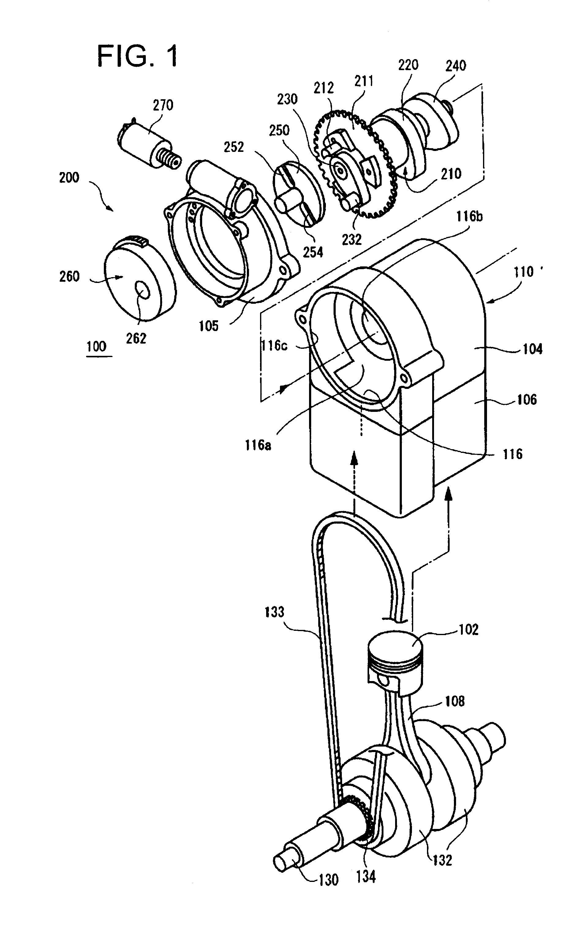
[0031]FIG. 1 shows an exploded perspective view of the substantial part of an engine provided with the variable valve drive device according to an embodiment of the present invention.

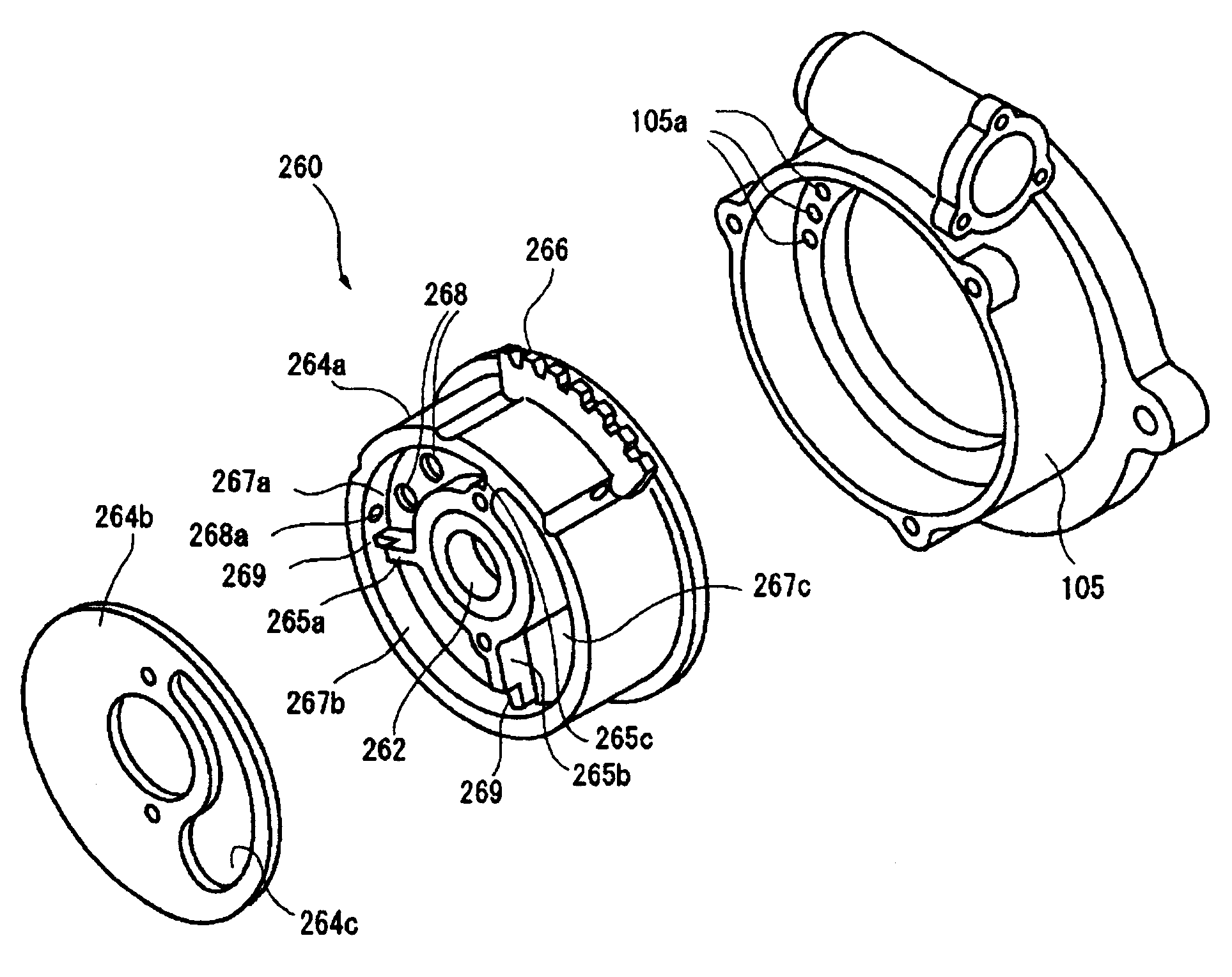
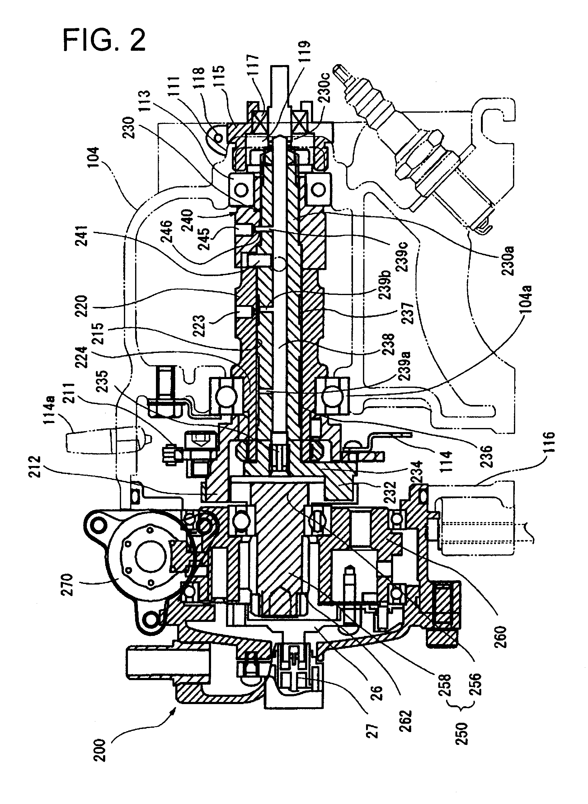
[0032]FIG. 1 shows an engine 100 that includes an engine main body 110 having a cylinder part 106 having slidably housed therein a piston 102 and a cylinder head 104, a crankshaft 130 housed in a crank case 112 (refer to FIG. 10), and a variable valve drive device 200.

[0033]In the engine 100, a periodical rotational phase difference is set up between an exhaust cam block 220 and an intake cam block 240 by the variable valve drive device 200 that is arranged substantially in parallel with the crankshaft 130 so as to make the opening and closing valve timing variable according to the respective rotations. Accordingly, the valve overlap is made variable according to the number o...


PUM


Abstract

In a variable valve drive device, a cam sprocket made to rotate by a driving force transmitted from a crankshaft. An eccentric plate is arranged at one end side of the cam sprocket in the rotation axis direction thereof, and is made to rotate around an axis in the same direction as the rotation axis of the cam sprocket. The axis of the eccentric plate is shiftable from the axile center of the rotation axis to an eccentric position. A variable camshaft is made to rotate around its rotation axis by the eccentric plate, and when the eccentric plate rotates the variable camshaft at the eccentric position, the rotational phase difference thereof with respect to the cam sprocket periodically fluctuates. An intake cam block is arranged at the other end side of the cam sprocket in the rotation axis direction thereof, and is made to rotate by the variable camshaft with the same phase as that of the variable camshaft to drive an intake valve.

Description

BACKGROUND OF THE INVENTION[0001]1. Field of the Invention[0002]The present invention relates to a variable valve drive device that is arranged in an engine, an engine, and a motorcycle.[0003]2. Description of the Related Art[0004]Conventionally, in the four-cycle engine, by changing the valve overlap or a period during which the intake valve and the exhaust valve are opened concurrently at the time of the high-speed rotation and the low-medium-speed rotation respectively, high output and low mileage of engine as well as reduction of exhaust gas are realized.[0005]As a mechanism to change the valve overlap depending on the rotation of an engine, there is known the variable valve timing mechanism that changes the opening and closing timing of the valves according to the number of revolutions of an engine.[0006]As a general variable valve timing mechanism, for example, there is known one mechanism in which, at the sprocket part for driving cams which rotates in conjunction with the ro...

Claims


Application Information

Patent Timeline
IPC IPC(8): F01L1/344
CPCF01L1/022F01L1/024F01L1/053F01L1/344F01L1/356F01L2001/0473F01L2820/032
Inventor TSUCHIDA, NAOKI
Owner YAMAHA MOTOR CO LTD
Why Eureka
Try Eureka