

Five Axis Compensated Rotating Stage
a technology of rotating stage and axis compensation, which is applied in the direction of electric programme control, dynamo-electric converter control, program control, etc., can solve the problem of difficult to achieve precision in rotating stag
- Summary
- Abstract
- Description
- Claims
- Application Information
AI Technical Summary
Benefits of technology
Problems solved by technology
Method used
Image

Examples
Embodiment Construction
[0016]Many other products utilize high precision linear motion control, but rotary motion control is less straight forward.
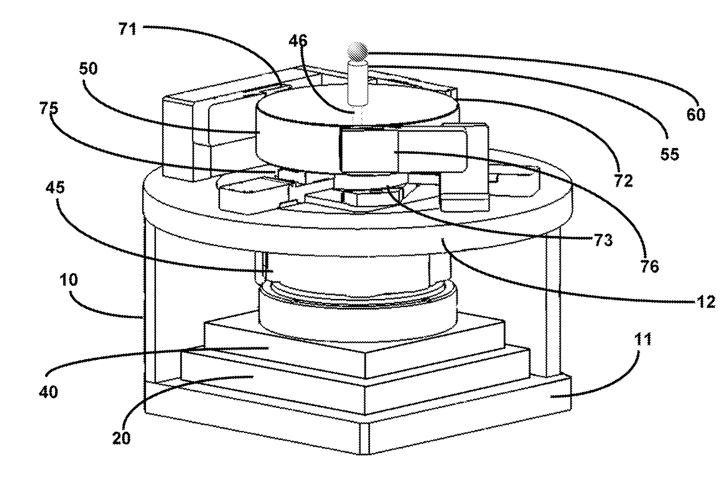
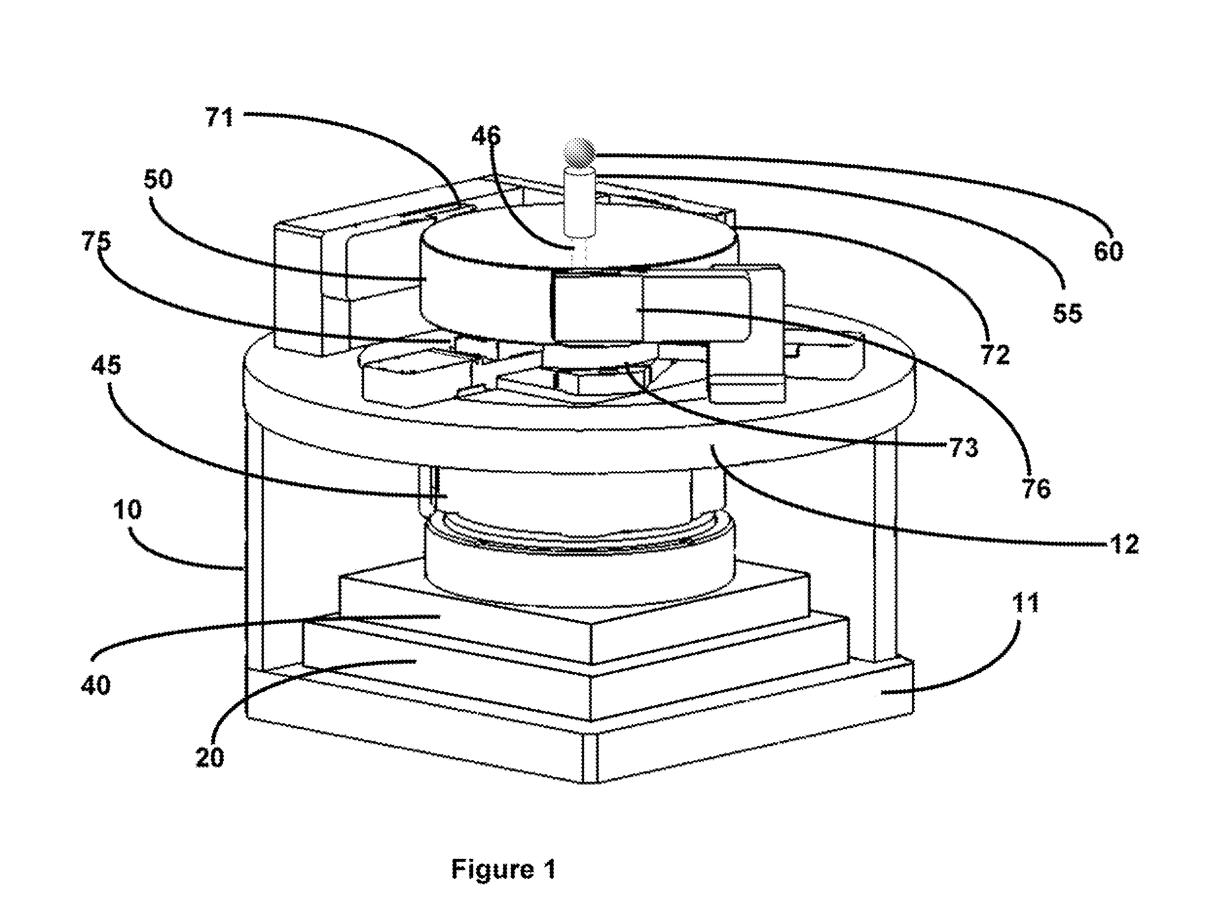
[0017]FIG. 1 shows a projection of the five axis compensated rotary stage assembly 10 comprised of a reference frame 11, with an actuator stage 20 attached to it, a rotation stage 40 containing a rotary motor 45, whose shaft is connected to a metrology disk 50. A sample 60, to be rotated, is placed upon the sample platform 55, attached to the center of the metrology disk 50. The rotary motor rotates the metrology disk 50, the sample platform 55 and the sample 60, relative to the reference frame 11. The actuator stage 20 contains five actuators to adjust the placement of the rotation stage 40 in five axes. The spindle shaft 46 of the rotary motor 45 extends through a hole in the top plate 12 of the reference frame 11. Six sensors 71, 72, 73, 75, and 76 (74 not shown) are mounted on fixed mechanical arms, which are attached to the top plate 12 of the reference fra...
PUM
 Abstract
Description
Claims
Application Information