Eureka AIR delivers breakthrough ideas for toughest innovation challenges, trusted by R&D personnel around the world.

High Voltage Power Switches Using Low Voltage Transistors

Active Publication Date: 2008-12-18
SNAPTRACK
View PDF8 Cites 6 Cited by
  • Summary
  • Abstract
  • Description
  • Claims
  • Application Information

AI Technical Summary

Benefits of technology

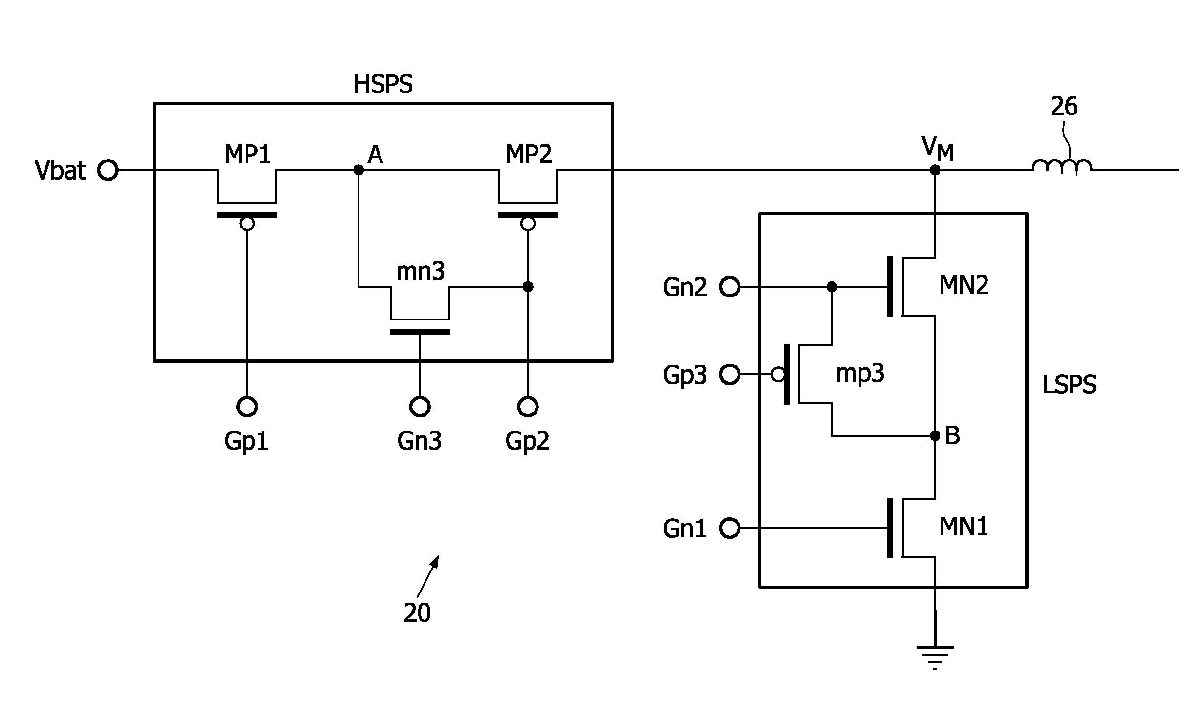
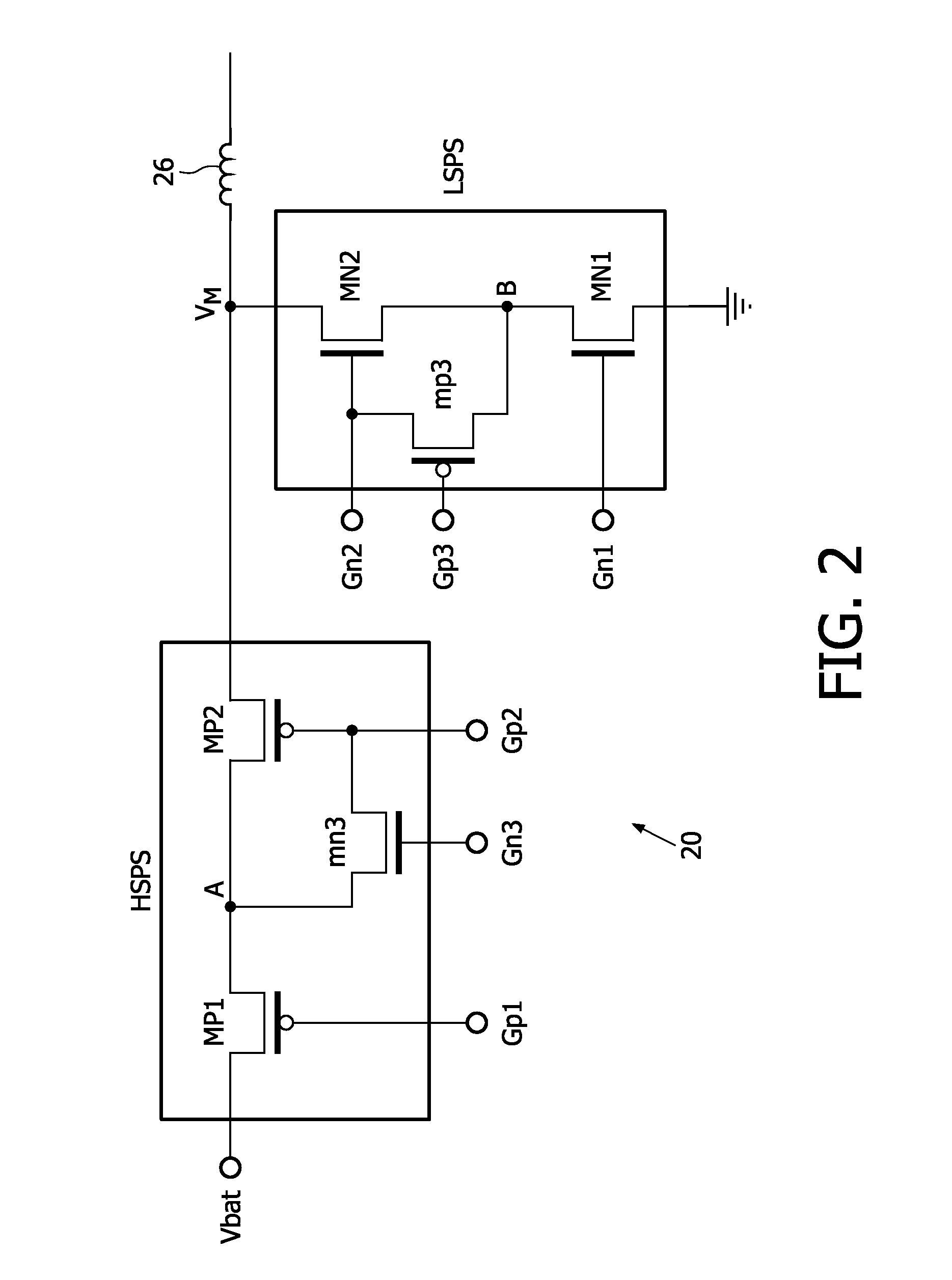
[0017]The switching regulator and the method of operating a switching regulator both operate to control the voltage across the terminals of the series-connected transistors of the power switches. Thus, the voltage across the transistors may be maintained at a level below the maximum permitted voltages for the transistors, and transistors having a maximum permitted voltage that is below the input voltage of the switching regulators can be safely used. The invention thus controls the voltages across the transistors and also operates efficiently under a varying battery voltage.

Problems solved by technology

The systems which use these circuits are getting more sophisticated and complex, their performance is increasingly enhanced and more features are being added, requiring more transistors to be integrated on a chip and higher computing power.
This incompatibility in supply voltage causes problems in system design and prevents microcontrollers from being powered directly by battery.
However, the maximum allowed voltage for CMOS transistors in the current state-of-the-art 65 nm process technology is only 2.5V.
In addition, various other high-voltage CMOS processes have been developed, but they are generally more expensive to use than standard CMOS processes, and are not used for microprocessors or DSPs.
However, such devices with an extended drain have to be characterized before they can be utilized.
Another drawback is that the extended drain only permits the drain-to-source voltage to be increased, whereas the maximum gate-to-source and gate-to-drain voltages are not affected and remain a problem.

Method used


Image

  • High Voltage Power Switches Using Low Voltage Transistors
  • High Voltage Power Switches Using Low Voltage Transistors
  • High Voltage Power Switches Using Low Voltage Transistors

Examples


Embodiment Construction

[0030]This invention explores circuit techniques and proposes a circuit arrangement for realizing high-voltage power switches using standard, low-voltage CMOS transistors. The idea is to distribute the high-voltage over two or more transistors connected in cascading. In this way, a 5V power switch, for example, can be implemented by cascading two switches each using 2.5V transistors. In designing a cascading power switch, some key technical issues have to be solved.

[0031]Cascoding alone does not solve the problem. For example, by connecting two MOS transistors in cascoding, the drain-to-source voltage of both transistors can be halved, similar to the extended-drain MOSFET. However, gate-to-source and gate-to-drain voltage need to be carefully designed to avoid overvoltage, and to drive the power switches on and / or off. In addition, the design should avoid merely shifting the high-voltage problem from the power switch to somewhere else, for example, the switch driver circuit. Another...


PUM


Abstract

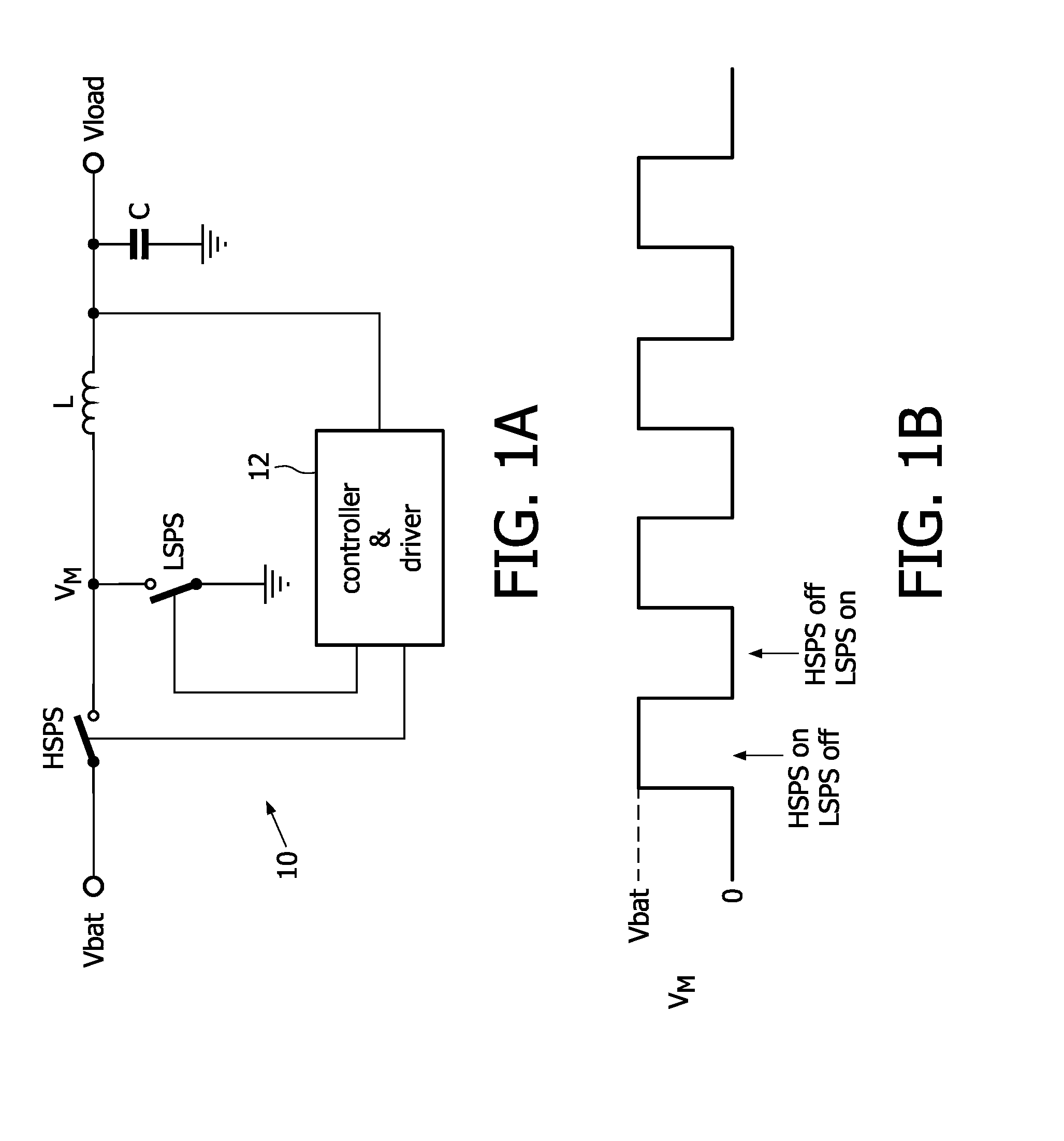
A switching regulator having first and second power switches. The first power switch has at least two transistors connected in series, the transistors having a first maximum voltage across their terminals which is less than the input voltage of the regulator. The transistors have at least a first node at the point where they are connected, and a first control circuit controls the voltage at the first node so that the voltages across the terminals of the transistors of the first power switch do not exceed the first maximum voltage. The second power switch also has at least two transistors connected in series, the transistors having a maximum voltage across their terminals that is less than the input voltage. The transistors have at least a second node at the point where they are connected, and a second control circuit controls the voltage at the second node so that the voltages across the terminals of the transistors of the second power switch do not exceed the second maximum voltage.

Description

FIELD OF THE INVENTION[0001]The invention relates to a high voltage power switch constructed using low voltage transistors. In particular, the invention relates to a switching regulator having first and second power switches, where each power switch has at least two transistors connected in series.BACKGROUND OF THE INVENTION[0002]Semiconductor manufacturing technology is driven by digital circuits such as microcontrollers, digital signal processors, memories, etc. The systems which use these circuits are getting more sophisticated and complex, their performance is increasingly enhanced and more features are being added, requiring more transistors to be integrated on a chip and higher computing power. To accommodate these needs while lowering costs, semiconductor device manufacturers have introduced ever smaller geometries in their semiconductor process to reduce transistor size and squeeze more transistors on a single silicon wafer.[0003]The smaller geometries require a correspondin...

Claims


Application Information

Patent Timeline
IPC IPC(8): G05F3/00
CPCH02M1/08H02M3/158H02M3/1582H03K17/102H03K17/6871
Inventor WANG, ZHENHUA
Owner SNAPTRACK
Why Eureka
Eureka Blog
Learn More