Vehicular meter unit and display device

a technology of display device and meter unit, which is applied in the direction of static indicating device, identification means, instruments, etc., can solve the problems of inconvenient use, limited display of meter, and inability to read the indication value directly, so as to achieve the effect of effective us

Active Publication Date: 2008-12-18
DENSO CORP
View PDF11 Cites 98 Cited by
  • Summary
  • Abstract
  • Description
  • Claims
  • Application Information

AI Technical Summary

Benefits of technology

[0043]With the configuration, when the display is switched between the first display image and the contraction image that is contracted from the first display image and that has the form different from the first display image, the display is switched to the intermediate image having the same size as the first display image and the form that is the same as or similar to the contraction image in the course of the switching of the display. In consequence, the changes in both of the form and the size of the image due to the switching of the display between the first display image and the contraction image can be separated into a change of the form of the image due to the switching of the display between the first display image and the intermediate image and a change of the size of the image due to the switching of the display between the contraction image and the intermediate image. Therefore, a change of the image due to the switching of the display between the first display image and the contraction image can be moderated.
[0044]According to another aspect of the present invention, the display device switches the display from the intermediate image to the contraction image by gradually contracting the intermediate image to a size of the contraction image. In consequence, a change in the size of the image due to the switching of the display from the intermediate image to the contraction image can be moderated. Accordingly, the change of the image due to the switching of the display from the first image to the contraction image can be further moderated.
[0045]According to another aspect of the present invention, the display device switches the display from the contraction image to the intermediate image by gradually enlarging the contraction image to the size of the intermediate image. In consequence, a change in the size of the image due to the switching of the display from the contraction image to the intermediate image can be moderated. Accordingly, the change of the image due to the switching of the display from the contraction image to the first display image can be further moderated.
[0046]According to yet another aspect of the present invention, when the display is switched to the contraction image, the display device displays a second display image indicating second information by using a region obtained by subtracting a region where the contraction image is indicated from a region where the first display image was indicated. In consequence, in addition to the aforementioned effects, the region produced by switching the display to the contraction image can be effectively used and therefore, many pieces of information can be displayed in a limited space.

Problems solved by technology

However, the pointer type meter has a disadvantage that reading accuracy of the indication value is inferior to that of a digital meter directly displaying the indication value in figures.
In the case where the image window such as the camera image or the map image is displayed on the display for displaying the meter, the meter is required to be displayed in a margin of the image window, so the display of the meter tends to be restricted.
However, this construction causes following defects (1) to (3) when the display mode is switched from the first display mode to the second display mode, for example.
Therefore, there is a possibility that a driver driving the vehicle while watching the digital speed meter loses the sight of the digital speed meter and feels confused.
Since the form and the position of the pointer type analog speed meter change at the same time when the display mode is switched to the second display mode, there is a possibility that the driver driving the vehicle while watching the pointer type analog speed meter needs some time to recognize that the pointer type analog speed meter in the second display mode is functionally equivalent to the pointer type analog speed meter in the first display mode and feels confused.
Therefore, there is a possibility that the driver needs some time to recognize that the display of the digital speed meter is continued in the position moved to the left end of the screen.
Moreover, in the case where the digital speed meter is displayed over the deformed pointer type analog speed meter, there is a disadvantage of difficulty in reading the digital speed meter.
It is because recognition becomes difficult if the display image is contracted in homogenous deformation and displayed without altering the form.
This problem occurs also when the display is switched from the contraction image to the display image.

Method used


Image

  • Vehicular meter unit and display device
  • Vehicular meter unit and display device
  • Vehicular meter unit and display device

Examples


second embodiment

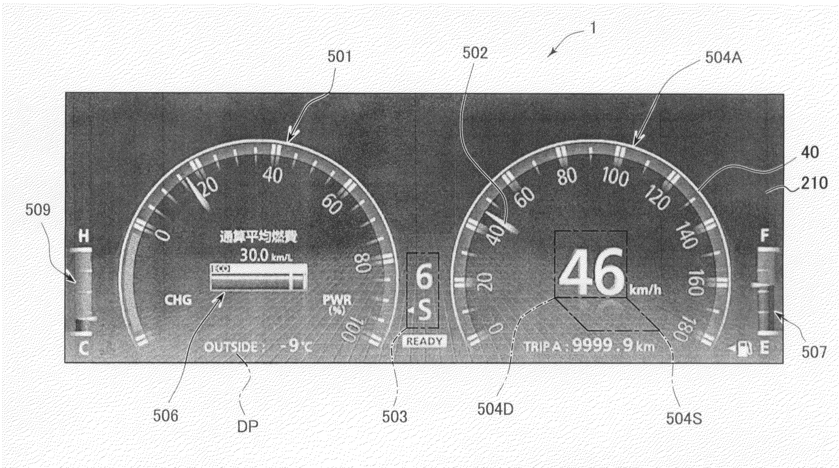
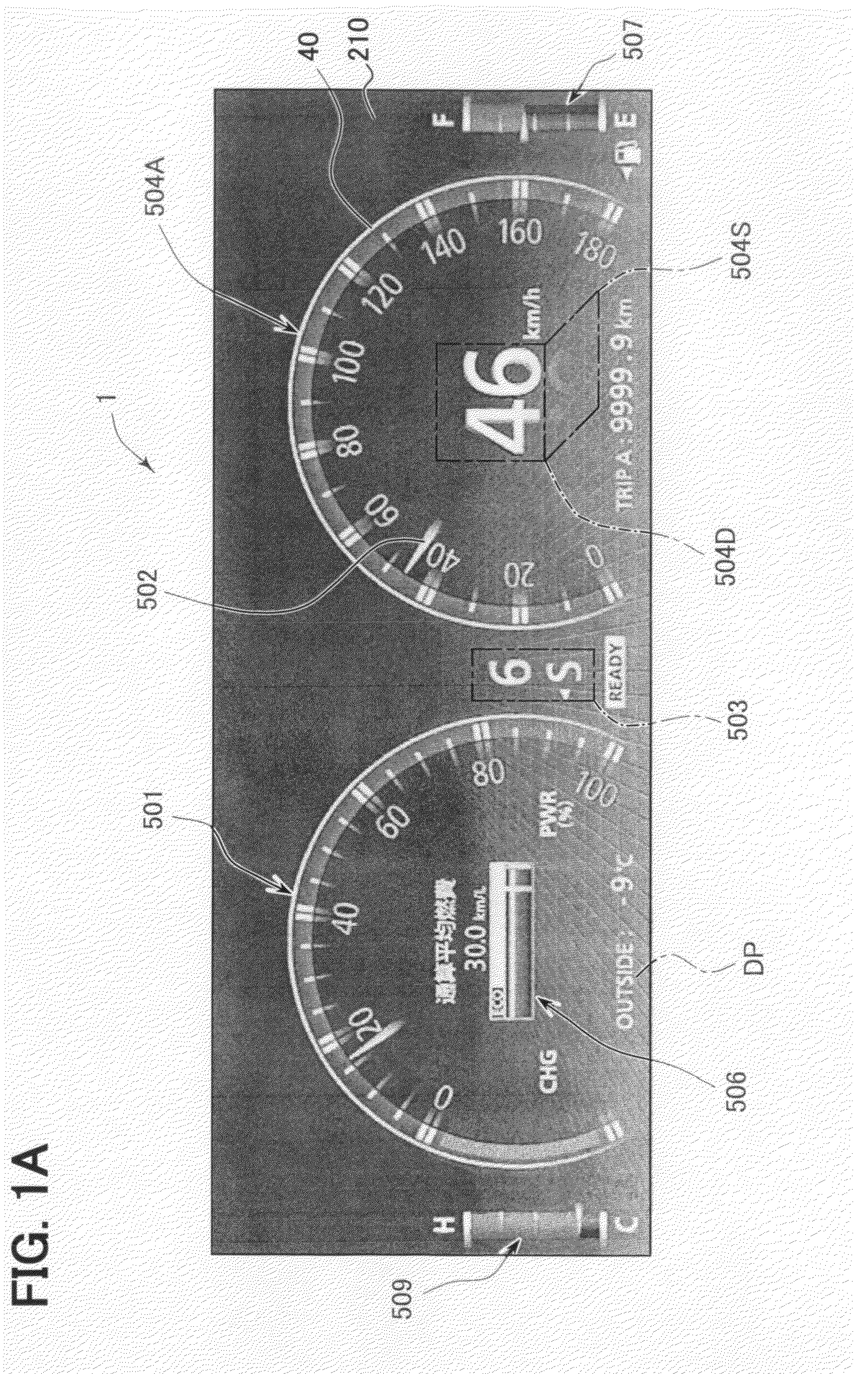
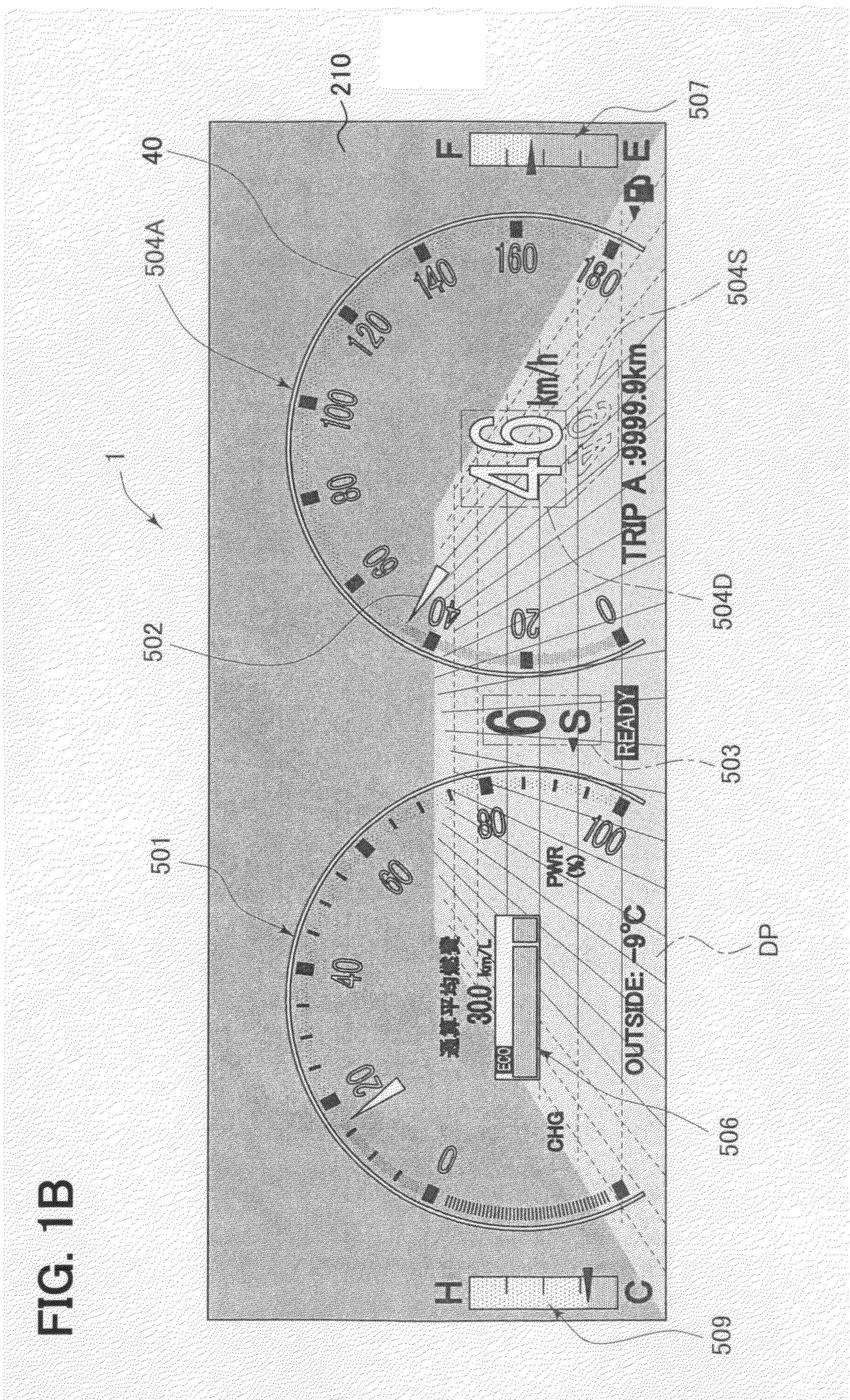
[0091]Next, the present invention will be described with reference to the drawings. FIG. 14 schematically shows an image processing sequence at the time when the display mode is switched from the first display mode shown in FIG. 1A to the second display mode shown in FIG. 2. As shown in a state 1, both of the digital speed meter 504D and the pointer type analog speed meter 504A are displayed in the first display mode. As contrasted thereto, the pointer type analog speed meter 504A is erased as the display mode is switched to the second display mode as shown in a state 2. In FIG. 14, image control is performed such that the image state displaying the pointer type analog speed meter 504A in the first display mode directly switches to the image state showing the completion of the erasure of the same as shown in the state 2 without going through an intermediate state. That is, the image control of completing the transition in a single frame is performed.

[0092]As shown in a state 3, the ...

first embodiment

[0097]Also, a mode transition animation can be displayed and output through execution of the meter drawing software when the display mode of the display 210 is switched from the first display mode of FIG. 1A to the second display mode of FIG. 2 as in the The mode transition animation includes a moving image of displaying the pointer type analog speed meter 504A and the pointer type analog output meter 501 constituting the first specific image function components in FIG. 1A such that the display state of the pointer type analog speed meter 504A and the pointer type analog output meter 501 gradually changes toward the erasure state shown in FIG. 2.

[0098]In this example, a convergence point of the image contraction is conceptually set in the intermediate position between the pointer type analog output meter 501 and the pointer type analog speed meter 504A with respect to the horizontal direction in which the meters 501, 504A are arranged side by side. The moving image processing is pe...

third embodiment

[0103]Next, a display device according to the present invention will be explained with reference to the drawings. A display device 601 shown in FIG. 18 is used as an in-vehicle display device, for example. The display device 601 has a liquid crystal panel 602 as a display panel, a light-emitting diode 603, CPU 604 (central processing unit) as a controller, a drawing IC 605 (integrated circuit), ROM 641 (read-only memory) and an image memory 651 capable of rewriting storage data.

[0104]The liquid crystal panel 602, in which multiple pixels 621 are formed in a matrix shape, is a liquid crystal panel of an active matrix type driven by a thin film transistor (TFT) (not shown). Each pixel 621 incorporates a red pixel, a green pixel and a blue pixel. Voltage is applied to a gate of the TFT to control voltage applied to the red pixel, the green pixel and the blue pixel in each pixel 621. Thus, respective optical transmittances of the red pixel, the green pixel and the blue pixel in each pix...


PUM


Abstract

In a first display mode, a common image function component is displayed to occupy at least a part of a display region of a second specific image function component. In a second display mode, the common image function component is continuously displayed outside the second specific image function component to avoid the overlap therebetween (i.e., such that an exclusive positional relationship is made therebetween). When the display mode is switched, a final transition of the display mode to a display state in the second display mode is made while or after a moving image showing a transition process, in which the common image function component is moved from a display position in the first display mode to a display position in the second display mode, is displayed as a mode transition animation.

Description

CROSS REFERENCE TO RELATED APPLICATION[0001]This application is based on and incorporates herein by reference Japanese Patent Applications No. 2007-97795 filed on Apr. 3, 2007, No. 2007-246369 filed on Sep. 24, 2007, and No. 2008-21562 filed on Jan. 31, 2008.BACKGROUND OF THE INVENTION[0002]1. Field of the Invention[0003]The present invention relates to a vehicular meter unit. The present invention also relates to a display device that switches a display of a display panel, in which multiple pixels are formed in a matrix shape, between a display image and a contraction image indicating the same information.[0004]2. Description of Related Art[0005]A meter is installed in a cockpit for a vehicle (particularly for an automobile) for displaying vehicle speed, engine rotation speed and the like. A classical analog mechanical pointer type meter is known as such the meter. Also, a meter unit that is constructed of a display such as a liquid crystal panel and that displays a color image of ...

Claims


Application Information

Patent Timeline
Patent Type & Authority Applications(United States)
IPC IPC(8): B60Q1/00
CPCB60K35/00B60K37/02B60K2350/1072B60K2350/403B60R1/00B60K2370/155B60K2370/1515
Inventor KUNO, MASAHIROMATSUNO, NAGAKO
Owner DENSO CORP
Why Eureka
Try Eureka