Nuclear Reactor, In Particular a Liquid-Metal-Cooled Nuclear Reactor

a liquid metal-cooled, nuclear reactor technology, applied in nuclear reactors, climate sustainability, nuclear energy generation, etc., can solve the problem of cumbersome system of fluid tightness between hot collector and cold collector, and achieve the effect of simple and fast removal and small space occupation

Inactive Publication Date: 2008-12-18
ANSALDO NUCLEARE
View PDF3 Cites 49 Cited by
  • Summary
  • Abstract
  • Description
  • Claims
  • Application Information

AI Technical Summary

Benefits of technology

[0010]In this way, it is possible to achieve all the advantages associated to the use of a cylindrical inner vessel, but with an added significant reduction (indicatively of approximately 30%) of the overall volume of the reactor and, hence, of the amount of primary fluid required for operation of the reactor. In fact, the system of fluid tightness between the hot collector and the cold collector is far from cumbersome, given that it is limited to the area of the inlet of the integrated assembly and does not have to be extended also to the areas of penetration of the heat exchangers through the inner vessel. In addition, the use of an integrated assembly that combines a number of components (the pump and one or more heat exchangers) entails a smaller occupation of space at the level of the penetrations on the roof of the reactor as compared to the use of independent components (pumps and heat exchangers). The solution according to the invention then enables a simple and fast removal of the integrated assembly from the reactor in the event of need.

Problems solved by technology

In fact, the system of fluid tightness between the hot collector and the cold collector is far from cumbersome, given that it is limited to the area of the inlet of the integrated assembly and does not have to be extended also to the areas of penetration of the heat exchangers through the inner vessel.

Method used


Image

  • Nuclear Reactor, In Particular a Liquid-Metal-Cooled Nuclear Reactor
  • Nuclear Reactor, In Particular a Liquid-Metal-Cooled Nuclear Reactor
  • Nuclear Reactor, In Particular a Liquid-Metal-Cooled Nuclear Reactor

Examples


Embodiment Construction

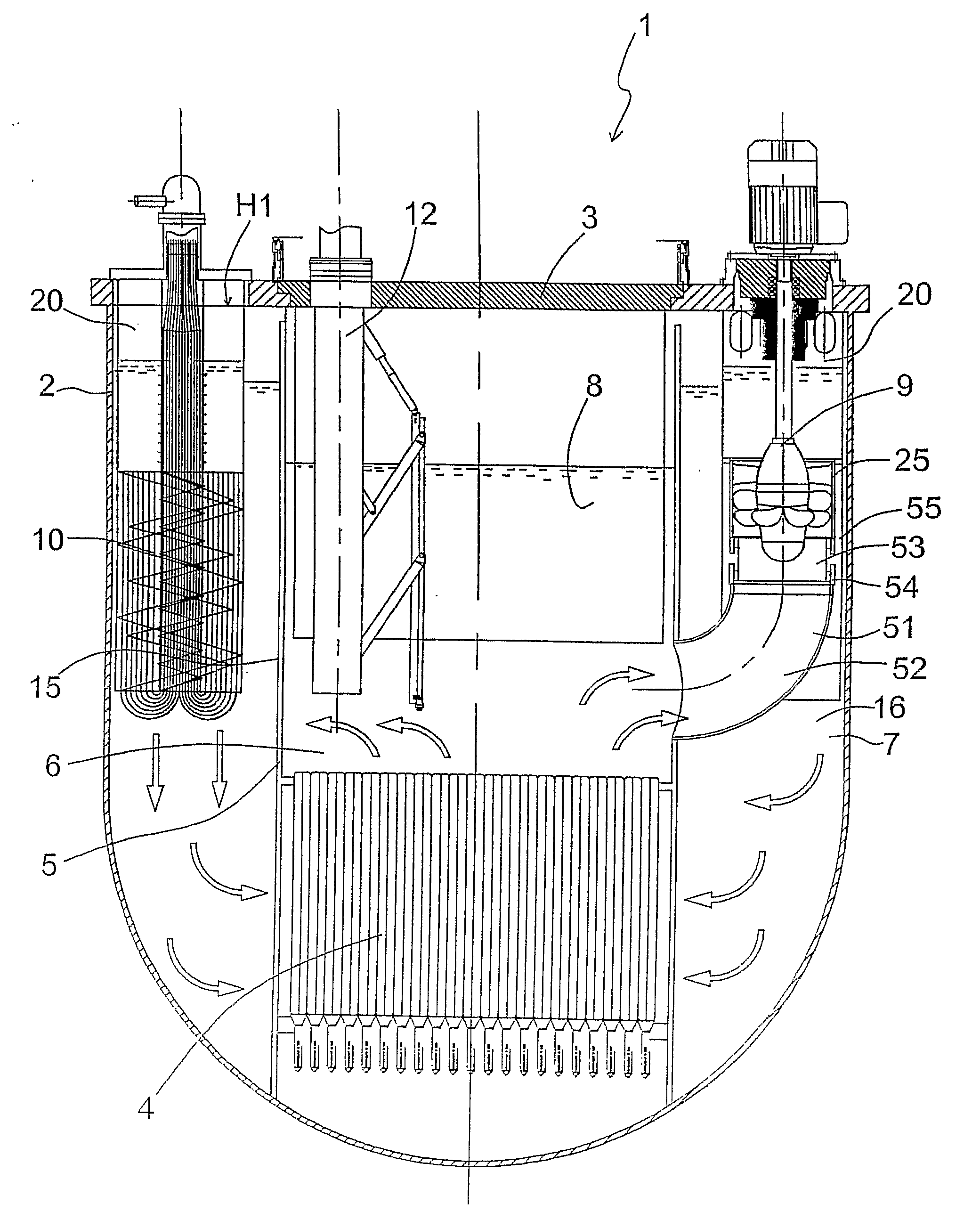
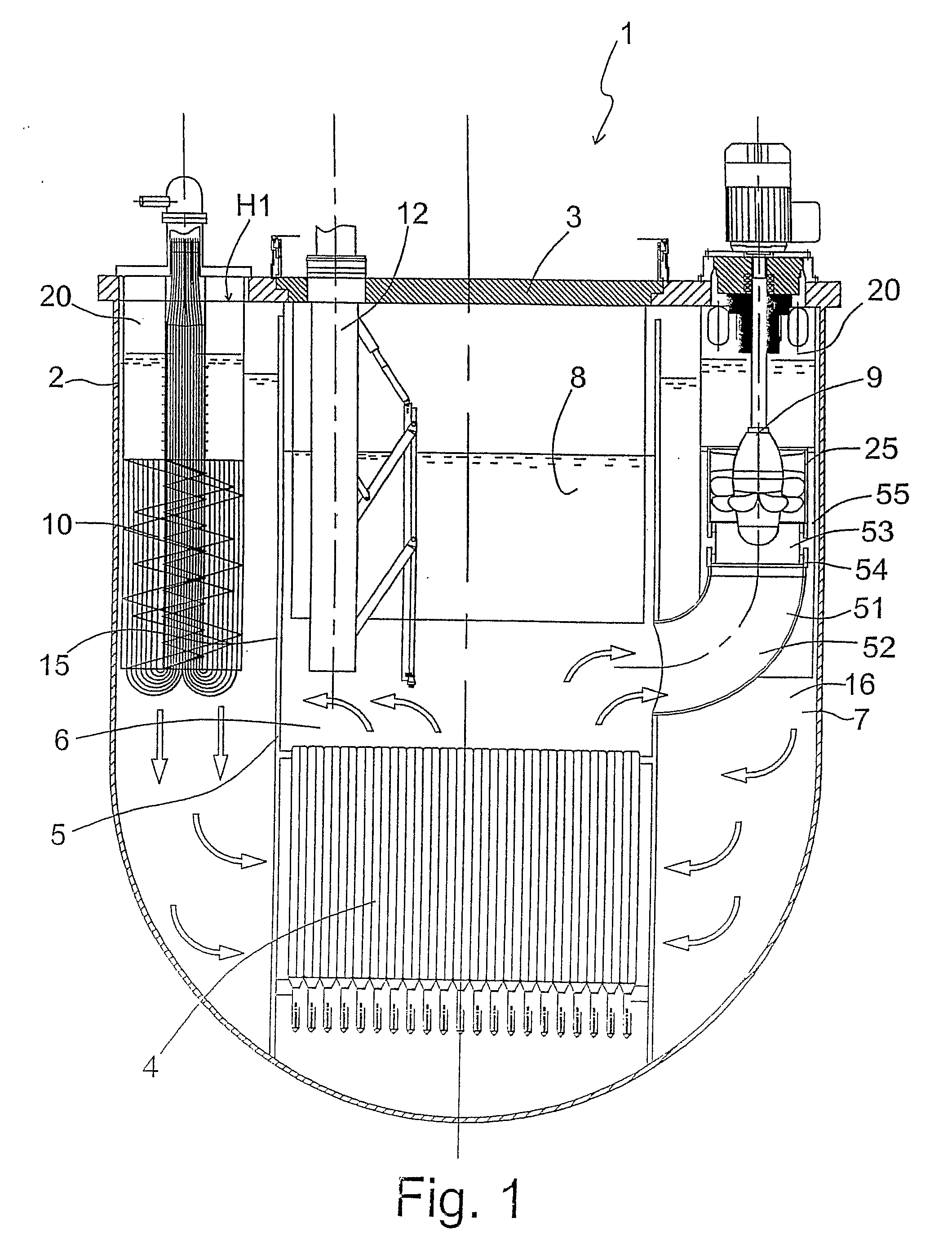
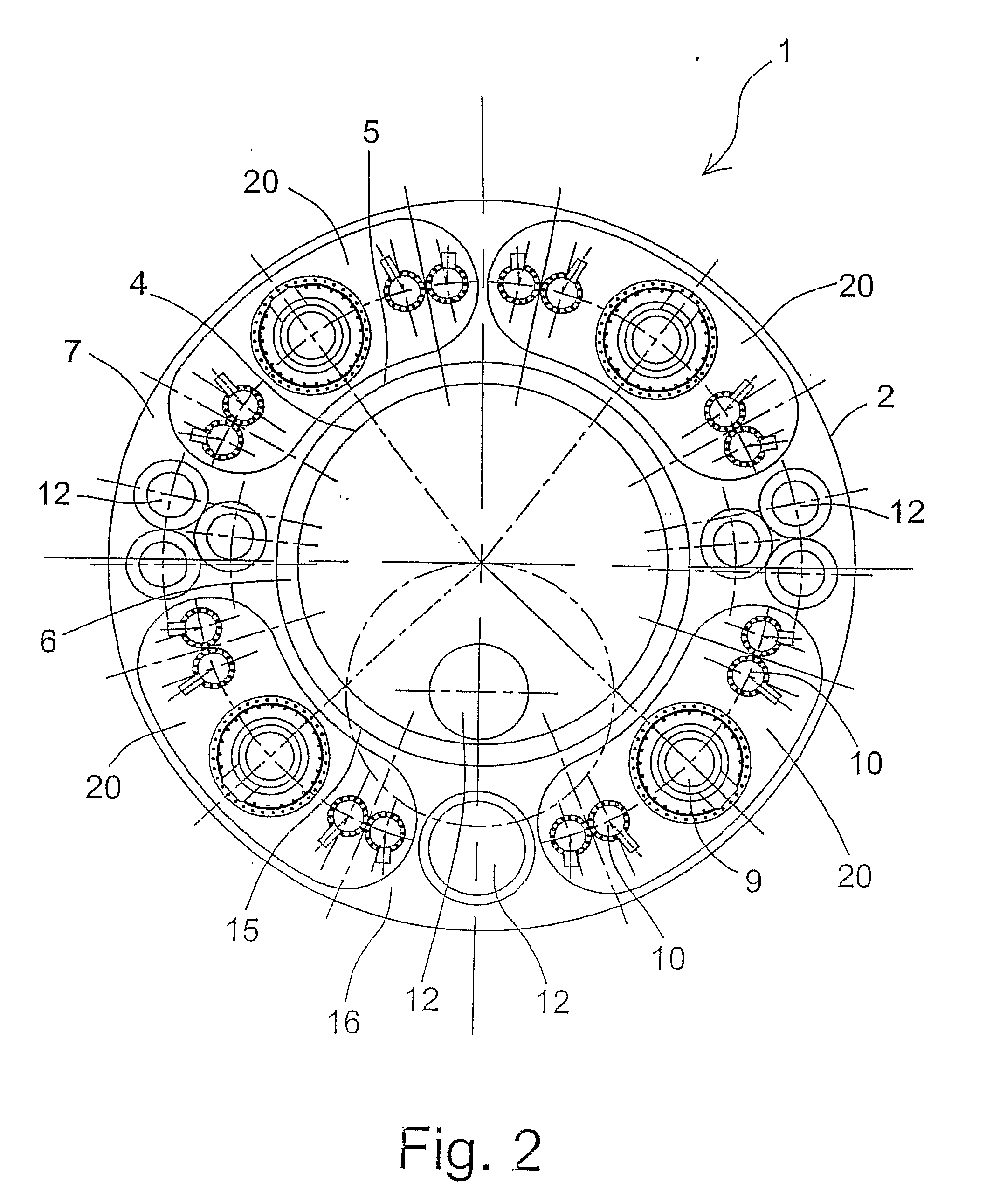
[0017]With reference to FIGS. 1 and 2, a nuclear reactor 1 comprises a casing or outer vessel 2 covered by a roof 3 and containing inside it a core 4 and a separation structure 5, defining a hot collector 6 and a cold collector 7, circulating in which is a primary fluid 8 for cooling the core 4. Housed inside the outer vessel 2 are then pumps 9 for circulation of the primary fluid 8 and heat exchangers 10, preferably steam generators, which are traversed by the primary fluid 8 and transfer the power generated in the core 4 to a secondary coolant circulating in a secondary external circuit (known and not illustrated).

[0018]Preferably, the primary fluid 8 is a liquid metal and in particular a heavy liquid metal, for example lead or lead-bismuth eutectic.

[0019]Housed within the outer vessel 2 are then various auxiliary devices 12, amongst which, for example, machines for transfer of the fuel, structures for supporting the instrumentation and the control bars, auxiliary heat exchangers ...


PUM


Abstract

A nuclear reactor (1) is provided, in particular a nuclear reactor cooled with a liquid metal (for example, a heavy liquid metal, such as lead or lead-bismuth eutectic), of the type having a cylindrical inner vessel (15) that divides a hot collector (6) over a core (4) from a substantially annular cold collector (7) surrounding the hot collector; housed in the cold collector (7) is a plurality of integrated circulation and heat-exchange assemblies (20), each of which includes a pump (9), two heat exchangers (10) set at the sides of the pump, and a conveying structure (21) through which a primary fluid (8) for cooling the core passes from the pump to the heat exchanger, all of which are fixedly connected to one another to form a unitary structure; each integrated assembly has an inlet (26) connected to the hot collector (6) and two outlet sections (34) in the cold collector (7).

Description

TECHNICAL FIELD[0001]The present invention relates to a nuclear reactor, in particular a liquid-metal-cooled nuclear reactor, preferably of the type with cylindrical inner vessel.BACKGROUND ART[0002]It is known that in fast nuclear reactors, which have the heat exchangers within the casing (“outer vessel”) of the reactor, there exists the need to separate the hot collector hydraulically from the cold collector to create a closed circuit for cooling the core.[0003]In the solutions currently adopted, the hydraulic-separation structure is constituted by an appropriately shaped metal shell, also referred to as “inner vessel”, having in general a complex shape and provided with a certain number of penetrations for housing pumps and heat exchangers.[0004]The main heat exchangers for the power of the reactor are immersed for the most part in the hot collector, in which the heat exchangers of the auxiliary circuits for evacuation of the residual power are also housed.[0005]The above solutio...

Claims


Application Information

Patent Timeline
Patent Type & Authority Applications(United States)
IPC IPC(8): G21C1/03
CPCG21C1/00G21C1/02G21C1/03G21Y2002/301G21Y2002/304G21Y2002/402G21Y2004/30Y02E30/35Y02E30/34Y02E30/30G21C15/24
Inventor CINOTTI, LUCIANO
Owner ANSALDO NUCLEARE
Why Eureka
Try Eureka