Communication system and communication apparatus

a communication system and communication technology, applied in the field of communication system and communication apparatus, can solve the problems of affecting communication, affecting communication, and affecting communication, and achieve the effects of stable data communication, short range, and favorable operation over a wideband band

Inactive Publication Date: 2008-12-18
SONY CORP
View PDF8 Cites 68 Cited by
  • Summary
  • Abstract
  • Description
  • Claims
  • Application Information

AI Technical Summary

Benefits of technology

[0046]In the communication system using magnetic field coupling that includes the transmitter and receiver including coils coupled in an inductive magnetic field and that performs noncontact communication through magnetic coupling in a short range, each of the coupling coils is placed inside a dielectric loss material or on a surface of the dielectric loss material. In this case, as in the noncontact communication system using electrical field coupling, radio waves are absorbed by a dielectric loss material when the dielectric loss material is around the coil. However, an inductive magnetic field is unlikely to be affected. Therefore, radio waves are absorbed by the dielectric loss material placed near the coupling coil, but radiation of unnecessary radio waves and an effect of disturbing radio waves coming from the outside can be suppressed, and stable data communication can be performed through magnetic field coupling between the transmitter and receiver in a short range.
[0047]According to an embodiment of the present invention, an excellent communication system and communication apparatus that cause electrical fie...

Problems solved by technology

However, generation of radio waves undesired in a radio communication system of RF interferes another radio communication system and causes malfunction of peripheral information apparatuses.
Also, disturbing radio waves from the outside may disturb communication.
In that case, however, the absorber also absorbs desired radio waves to transmit desired signals, w...

Method used


Image

  • Communication system and communication apparatus
  • Communication system and communication apparatus
  • Communication system and communication apparatus

Examples


Embodiment Construction

[0082]Hereinafter, an embodiment of the present invention is described with reference to the drawings.

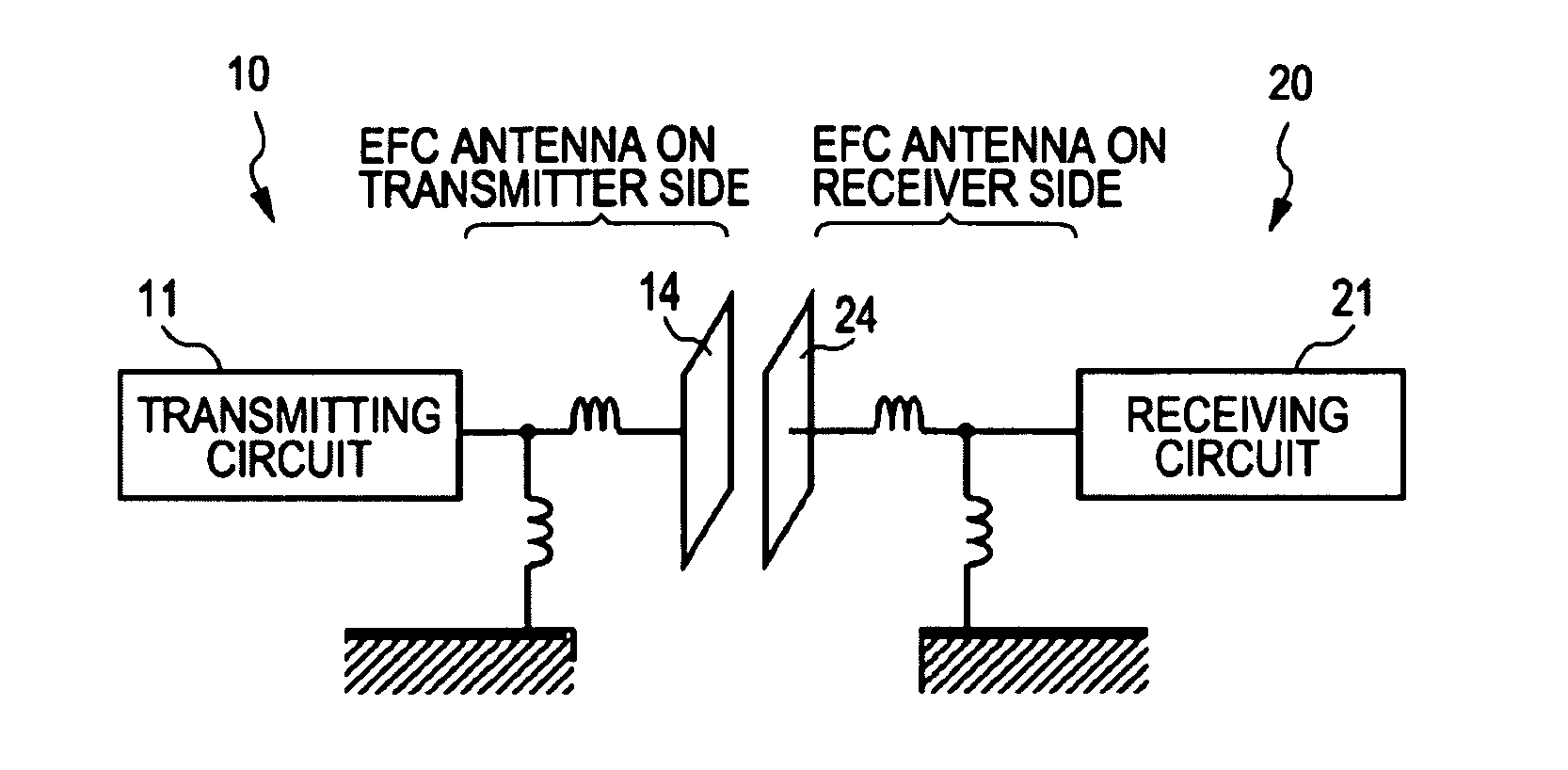
[0083]The present invention relates to a communication system to perform data transmission between information apparatuses by using electrical field coupling in an electrostatic field or an inductive electrical field. According to a communication method based on an electrostatic field or an inductive electrical field, no coupling relationship arises and no radio waves are emitted when no other end of communication exists in the neighborhood. Accordingly, any communication system is not disturbed. Furthermore, even if radio waves come from a remote site, a coupler does not receive the radio waves and thus interference by another communication system can be avoided.

[0084]In radio wave communication using an antenna according to a related art, the intensity of a radiated electrical field is inversely proportional to a distance from the antenna. On the other hand, the intensity of an in...


PUM


Abstract

A communication system includes a transmitter including a transmitting circuit to generate radio frequency signals for transmitting data and an electrical field coupling antenna to transmit the radio frequency signals as an electrostatic field or an inductive electrical field; and a receiver including an electrical field coupling antenna and a receiving circuit to perform a reception process on radio frequency signals received by the electrical field coupling antenna. Each of the electrical field coupling antennas of the transmitter and the receiver includes a coupling electrode, a resonant portion to strengthen electrical coupling between the coupling electrodes, and a radio wave absorber placed near the coupling electrode. The radio frequency signals are transmitted through electrical field coupling between the electrical field coupling antennas facing each other of the transmitter and the receiver.

Description

CROSS REFERENCES TO RELATED APPLICATIONS[0001]The present invention contains subject matter related to Japanese Patent Application JP 2007-157906 filed in the Japanese Patent Office on Jun. 14, 2007, the entire contents of which are incorporated herein by reference.BACKGROUND OF THE INVENTION[0002]1. Field of the Invention[0003]The present invention relates to a communication system and a communication apparatus allowing information apparatuses to perform large-volume data communication. Particularly, the present invention relates to a communication system and a communication apparatus allowing information apparatuses to perform data communication by using an electrostatic field or an inductive electrical field without causing interference with another communication system. Also, the present invention relates to a communication system and a communication apparatus allowing information apparatuses to perform data communication by using an inductive magnetic field without causing inte...

Claims


Application Information

Patent Timeline
IPC IPC(8): H04B5/00H04B1/719H04B5/02H04B13/00H04J13/00
CPCH01P1/203H01Q1/007H01Q1/248H01Q1/52H01Q3/267H01Q9/28H01Q17/00
Inventor WASHIRO, TAKANORI
Owner SONY CORP
Why Eureka
Try Eureka