Data communication device, data communication system, and data communication method

a data communication and data communication technology, applied in the field of data communication devices, data communication systems, and data communication methods for communications, can solve the problems of delay in an internal circuit, inability to stably operate the data carrier device b>900/b>, and difficult to completely suppress the phase difference between the pulse voltage va, etc., to achieve stable data communication, reduce the size of the system, and simple circuit configuration

Inactive Publication Date: 2007-12-13
CANON KK
View PDF8 Cites 8 Cited by
  • Summary
  • Abstract
  • Description
  • Claims
  • Application Information

AI Technical Summary

Benefits of technology

[0028]Using the following units, two terminals enable bi-directional data communications, thereby downsizing the system. In addition, with a simple circuit configuration without strict precision, a stable data communication that hardly causes a malfunction can be realized.

Problems solved by technology

However, the above-mentioned conventional data carrier device has the following problems.
As a result, there is the problem that the data carrier device 900 cannot be stably operated.
In the actual configuration of the system, there often occurs a delay in an internal circuit between the timing of outputting a pulse voltage VA and the timing of outputting a pulse voltage VB in the control device.
Therefore, it is very difficult to completely suppress the phase difference between the pulse voltage VA input to the terminal A and the pulse voltage VB input to the terminal B.
Therefore, when the circuit of the slave 2 operates with the data-superposed voltage as a power supply voltage, the power supply voltage largely fluctuates, thereby causing the operation of the internal circuit of the slave 2 to be unstable.
Therefore, it is difficult to perform stable data communication.
As a result, the system becomes large and costly.
Therefore, the fall time or the rise time of the output voltage indicates a sharp change, and the configuration is not satisfactory for a moderate change of an output waveform.

Method used


Image

  • Data communication device, data communication system, and data communication method
  • Data communication device, data communication system, and data communication method
  • Data communication device, data communication system, and data communication method

Examples


first embodiment

of the Present Invention

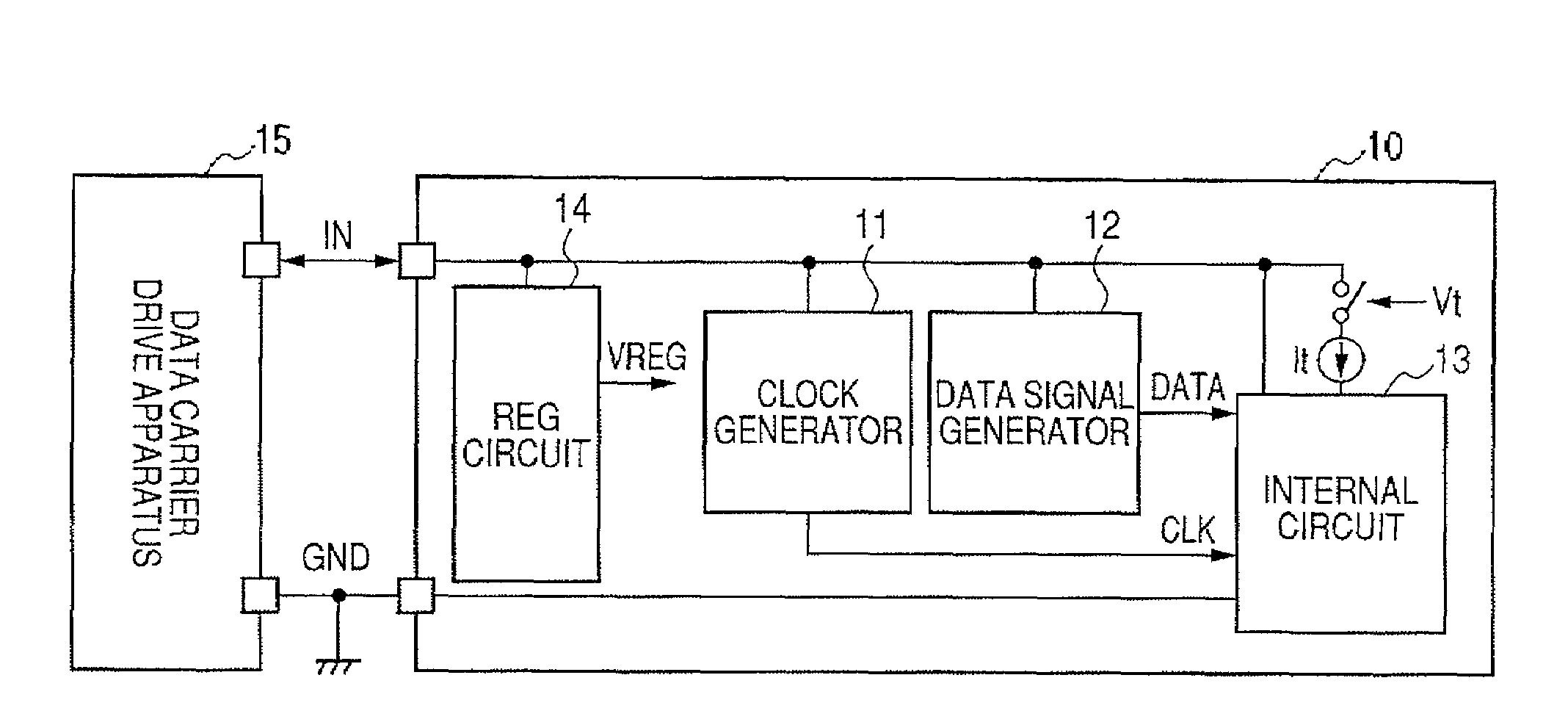
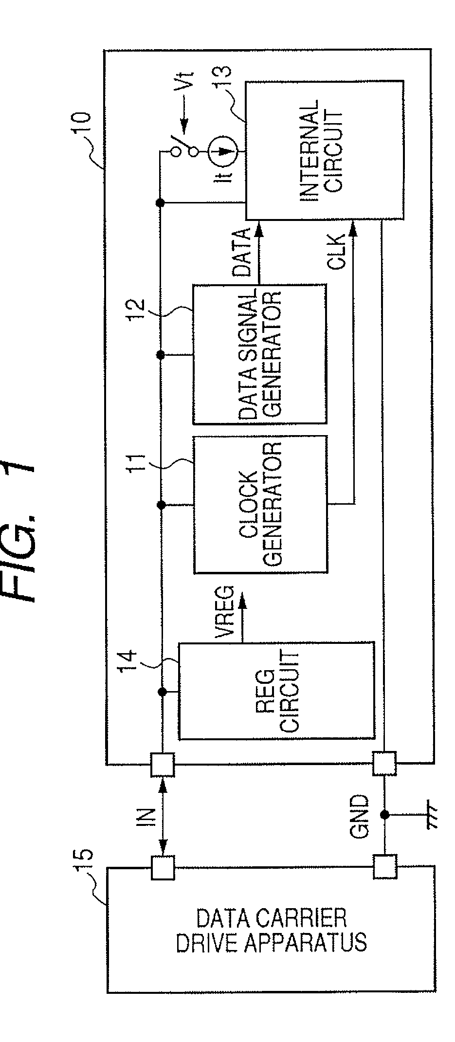
[0056]FIG. 1 is a block diagram showing the data communication system including a data carrier device (data communication device) 10 and its drive device (data communication device) 15 according to a first embodiment of the present invention. In FIG. 1, the data carrier device 10 performs data communications with the control device (data carrier drive device) 15 using two connection points, and has two terminals of an IN terminal (signal terminal) and a ground (GND) terminal (reference voltage terminal). The data carrier drive device 15 functions as a control device. The data carrier drive device 15 and the data carrier device 10 are connected by only two connection points of the IN terminal and the GND terminal, and perform the data communication through the two connection points. The data carrier device 10 generates the power supply for all circuits forming the data carrier device 10 from a signal input between the IN terminal and the GND terminal of the da...

second embodiment

of the Present Invention

[0081]FIG. 6 is a block diagram showing an example of the configuration of the data carrier device 20 according to a second embodiment of the present invention. The data carrier device 20 includes a regulator circuit 32 for outputting a power supply voltage of an internal circuit, a level shift circuit 33 in the clock generation circuit 21, a reference voltage circuit 31 for generating a reference voltage Vb of the circuits, and a current control circuit 34. The reference voltage Vb is a voltage generated in the data carrier device 20, and is generated by a band gap reference voltage generation circuit for generating, for example, a band gap reference voltage. The current control circuit 34 corresponds to the switch circuit in the internal circuit 13 shown in FIG. 1, and controls the current as a data transmission unit according to the output signal Vs of the level shift circuit 33. FIG. 6 illustrates the configuration of the circuit including the reference v...

third embodiment

of the Present Invention

[0091]FIG. 10 illustrates examples of circuits of the regulator circuit 32 in the data carrier device 20 and the level shift circuit 33 and the reference voltage circuit 31 in the clock generation circuit 21 according to a third embodiment of the present invention. The present embodiment of the present invention practically shows the regulator circuit 32 and the level shift circuit 33. In the circuit shown in FIG. 10, there is a voltage source Vb as the reference voltage circuit 31. The voltage source Vb is, for example, a band gap reference voltage generation circuit for generating, for example, a band gap reference voltage.

[0092]As the regulator circuit 32, the voltage source Vb is input as a reference voltage to a − side input terminal of the amplifier circuit AMP, and the output terminal of the amplifier circuit AMP is connected to the gate terminal of the PMOS (P channel MOS field effect transistor) M1. The source terminal of the transistor M1 is connect...


PUM


Abstract

A data communication device performs stable data communications without a malfunction in a system downsized by realizing bi-directional data communications using two terminals. The data communication device includes: a signal terminal (IN) for inputting a received signal having portions of different duty ratios and a constant pulse frequency; a reference voltage terminal (GND) for inputting a first reference voltage; a clock generation circuit for generating a clock signal according to the received signal; a data signal generation circuit for generating a data signal by identifying a duty ratio of the received signal; a transmission circuit for outputting a transmission signal to the signal terminal; and a regulator circuit for generating power supply voltages of the clock generation circuit, the data signal generation circuit, and the transmission circuit on a basis of an internally generated second reference voltage, the received signal, and the first reference voltage.

Description

BACKGROUND OF THE INVENTION[0001]1. Field of the Invention[0002]The present invention relates to a data communication device, a data communication system, and a data communication method for communications in the field of FA (factory automation) and the like.[0003]2. Description of the Related Art[0004]FIG. 21 illustrates the rough configuration of the conventional data communication system. In the configuration shown in FIG. 21, when a data carrier device 802 and a control device 801 perform data communications, four connection points are provided for each of a power supply VIN, a ground GND, a clock signal CLK, and a data signal DATA.[0005]In a system in which a control device and a data carrier device perform data communications, there is a configuration for downsizing the system with two connection points used for bi-directional data communications.[0006]For example, Japanese Patent Application Laid-Open No. 2003-069653 as a Japanese Patent describes the configuration.[0007]FIG....

Claims


Application Information

Patent Timeline
Patent Type & Authority Applications(United States)
IPC IPC(8): G06F1/00H04L25/03H04L25/49
CPCH03K7/08H04L25/08H03K19/003
Inventor YAMAZAKI, YOSHIKAZU
Owner CANON KK
Why Eureka
Try Eureka