Multi-hazard alarm system using selectable power-level transmission and localization

a multi-hazard, power-level technology, applied in the field of personal alarm systems, can solve the problems of limited battery space, battery's useful life is still, and the remote unit of most child monitoring systems is typically quite small, so as to prolong the battery life of the remote unit, the effect of rapid and precise positioning of the remote uni

Inactive Publication Date: 2008-12-18
CONVERSANT INTPROP MANAGEMENT INC
View PDF89 Cites 32 Cited by
  • Summary
  • Abstract
  • Description
  • Claims
  • Application Information

AI Technical Summary

Benefits of technology

[0034]It is an advantage of the present invention to periodically test system integrity by exchanging an electronic handshake and giving an alarm in the event of failure.
[0035]It is also an advantage of the present invention to prolong the remote unit battery life by transmission at low power in the absence of a defined emergency.
[0036]It is also an advantage of the present invention that the system is able to detect and give alarm for a number of common and dangerous hazards.
[0037]It is a further advantage of the present invention to permit rapid and precise location of the remote unit which is equipped with a GPS receiver.

Problems solved by technology

These hazards include the child's wandering away from a safe or supervised area, water emersion, fire, smoke inhalation, carbon monoxide poisoning and electrical shock.
The remote unit of most child monitoring systems is typically quite small and the available space for a battery is therefore quite limited.
Though the use of very low power electronic circuits has made possible the use of smaller batteries, a battery's useful life is still very much a factor of its physical size, which, as stated above, is limited because of the small size of a typical remote unit.

Method used


Image

  • Multi-hazard alarm system using selectable power-level transmission and localization
  • Multi-hazard alarm system using selectable power-level transmission and localization
  • Multi-hazard alarm system using selectable power-level transmission and localization

Examples


Embodiment Construction

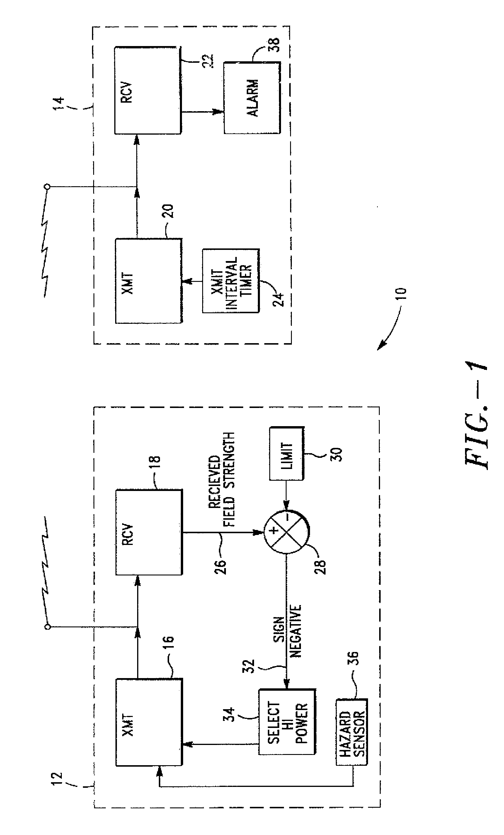
[0090]With reference to FIG. 1, there is shown a block diagram of a personal alarm system according to one embodiment of the present invention and depicted generally by the numeral 10. The personal alarm system 10 includes a remote unit 12 and a base station 14. The remote unit 12 has a radio transmitter 16 and a receiver 18, and the base station 14 has a radio transmitter 20 and a receiver 22. The transmitters 16, 20 and receivers 18, 22 are compatible for two-way radio communication between the remote unit 12 and the base station 14.

[0091]In a preferred embodiment, the base station 14 includes an interval timer 24 which causes the transmitter 20 to transmit at predetermined intervals. The receiver 13 of the remote unit 12 receives the signal transmitted by the base station 14 and causes the transmitter 16 to transmit a response to complete an electronic handshake.

[0092]The remote unit transmitter 16 is capable of transmitting at an energy conserving low-power level or at an emerge...


PUM


Abstract

A personal alarm system includes a monitoring base station and one or more remote sensing units in two-way radio communication. An electronic handshake between the base station and each remote unit is used to assure system reliability. The remote units transmit at selectable power levels. In the absence of an emergency, a remote unit transmits at a power-conserving low power level. Received field strength is measured to determine whether a remote unit has moved beyond a predetermined distance from the base station. If the distance is exceeded, the remote unit transmits at a higher power level. The remote unit includes sensors for common hazards including water emersion, smoke, excessive heat, excessive carbon monoxide concentration, and electrical shock. The base station periodically polls the remote units and displays the status of the environmental sensors. The system is useful in child monitoring, for use with invalids, and with employees involved in activities which expose them to environmental risk. Alternative embodiments include a panic button on the remote unit for summoning help, and an audible beacon on the remote unit which can be activated from the base station and useful for locating strayed children. In another embodiment, the remote unit includes a Global Positioning System receiver providing location information for display by the base station.

Description

RELATED APPLICATIONS[0001]This application is a continuation application that claims the benefit under 35 U.S.C. § 120 of U.S. application Ser. No. 11 / 493,935 entitled “MULTI-HAZARD ALARM SYSTEM USING SELECTABLE POWER-LEVEL TRANSMISSION AND LOCALIZATION,” filed on Jul. 25, 2006, which is a continuation application that claims the benefit under 35 U.S.C. § 120 of U.S. application Ser. No. 10 / 695,560, entitled “SELF-LOCATING ALARM SYSTEM EQUIPPED PARACHUTE,” filed on Oct. 27, 2003, which is a continuation-in-part of U.S. application Ser. No. 10 / 216,033, entitled “PORTABLE, SELF-LOCATING SMART DEFRIBILLATOR SYSTEM,” filed on Aug. 10, 2002, which is a continuation-in part of U.S. application Ser. No. 10 / 010,971, entitled “SELF-LOCATING ALARM SYSTEM EQUIPPED PARACHUTE,” filed on Dec. 4, 2001, which is a continuation-in-part of U.S. application Ser. No. 09 / 728,167, entitled “VOICE-ACTIVATED PERSONAL ALARM”, filed on Dec. 1, 2000, which is a continuation-in-part of U.S. application Ser. No...

Claims


Application Information

Patent Timeline
Patent Type & Authority Applications(United States)
IPC IPC(8): H04M11/04A61N1/08A61N1/39H04W4/90B63C9/00G08B13/14G08B19/00G08B21/02G08B25/01G08B25/10G08B26/00
CPCA61N1/08B63C9/0005G08B13/1427G08B19/00G08B21/0211G08B21/0227G08B21/023G08B21/0255G08B21/028G08B21/0283G08B21/0286G08B21/0288G08B21/0294G08B21/088G08B25/016G08B25/10G08B26/007H04W4/22H04W4/90
Inventor SCHLAGER, DANBARINGER, WILLIAM B.
Owner CONVERSANT INTPROP MANAGEMENT INC
Why Eureka
Try Eureka