Swing Drive Device and Work Machine

a drive device and drive shaft technology, applied in the direction of fluid couplings, servomotors, couplings, etc., can solve the problem of not being able to feed excess energy generated in the swing system directly to the hydraulic actuator, and achieve the effect of efficient input driving power, increased boom raising action speed, and effective recovery of return fluid discharged energy

Inactive Publication Date: 2008-12-25
CATEPILLAR SARL
View PDF3 Cites 47 Cited by
  • Summary
  • Abstract
  • Description
  • Claims
  • Application Information

AI Technical Summary

Benefits of technology

[0017]According to the present invention, by disengaging the clutch, the energy recovery motor driven by return fluid discharged from the boom cylinder is enabled to efficiently input driving power to the boom motor generator, which is under no-load condition, resulting in the generated electric power being stored in the electric power storage device of the hybrid type drive system. It is thus possible to effectively recover energy of return fluid discharged from the boom cylinder. When the clutch is engaged, electric power fed from the electric power storage device enables the boom motor generator to function as an electric motor to drive the boom assist pump so that hydraulic fluid is fed from the boom assist pump to the boom cylinder. As a great amount of hydraulic fluid is thus fed to the boom cylinder not only from the main pump and the swing pump motor functioning as a pump but also from the boom assist pump, the speed of boom raising action is further increased, resulting in further increased working efficiency.
[0018]According to the present invention, the solenoid valve between stick and boom is disposed in the circuit-to-circuit communicating passage between stick and boom for providing fluid communication between the hydraulic fluid feeding passage for the stick cylinder and the head-side of the boom cylinder. Therefore, by opening this solenoid valve, supply of hydraulic fluid to the boom cylinder is ensured, thereby increasing the speed of boom raising action by the boom cylinder and improving working efficiency. Furthermore, supply of hydraulic fluid to the stick cylinder can be ensured by closing the solenoid valve.
[0019]According to the present invention, the solenoid valve between bucket and boom is disposed in the boom cylinder hydraulic fluid feeding passage. Therefore, by opening thi

Problems solved by technology

However, in cases where actuators other than those of the swing system are hydraulic actuators, which are adapted to function by receiving hydraulic fluid, i

Method used


Image

  • Swing Drive Device and Work Machine
  • Swing Drive Device and Work Machine
  • Swing Drive Device and Work Machine

Examples


Embodiment Construction

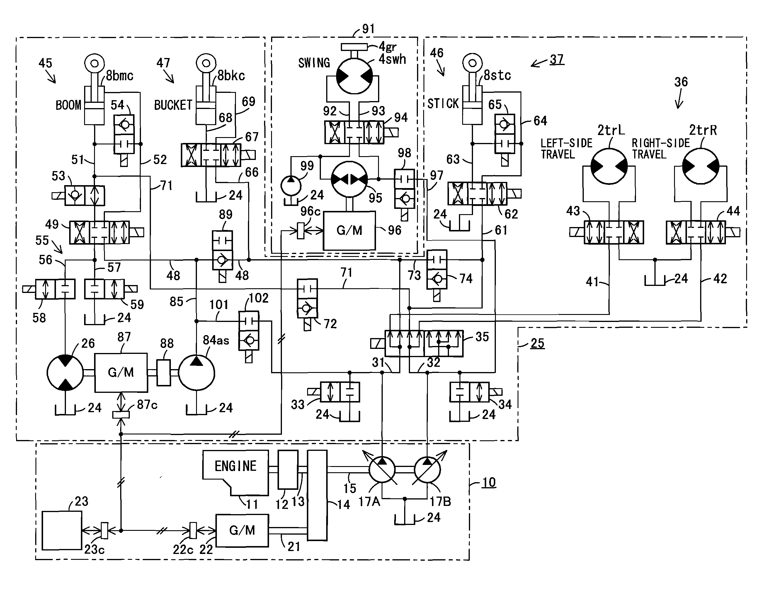
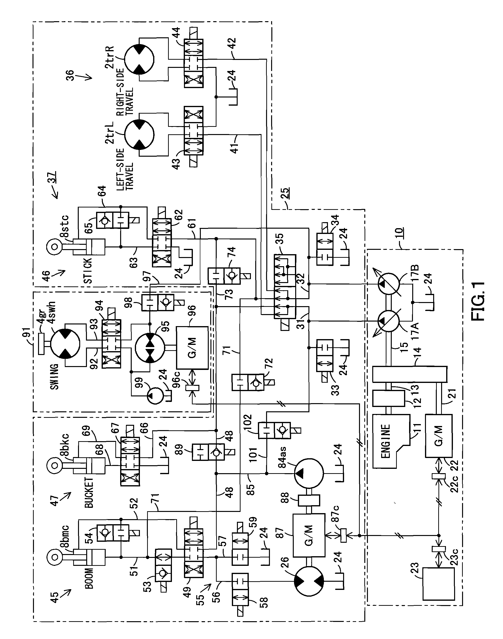
[0022]Next, the present invention is explained in detail hereunder, referring to an embodiment thereof shown in FIGS. 1 and 2. The fluid and fluid pressure used in this embodiment are oil and oil pressure, respectively.

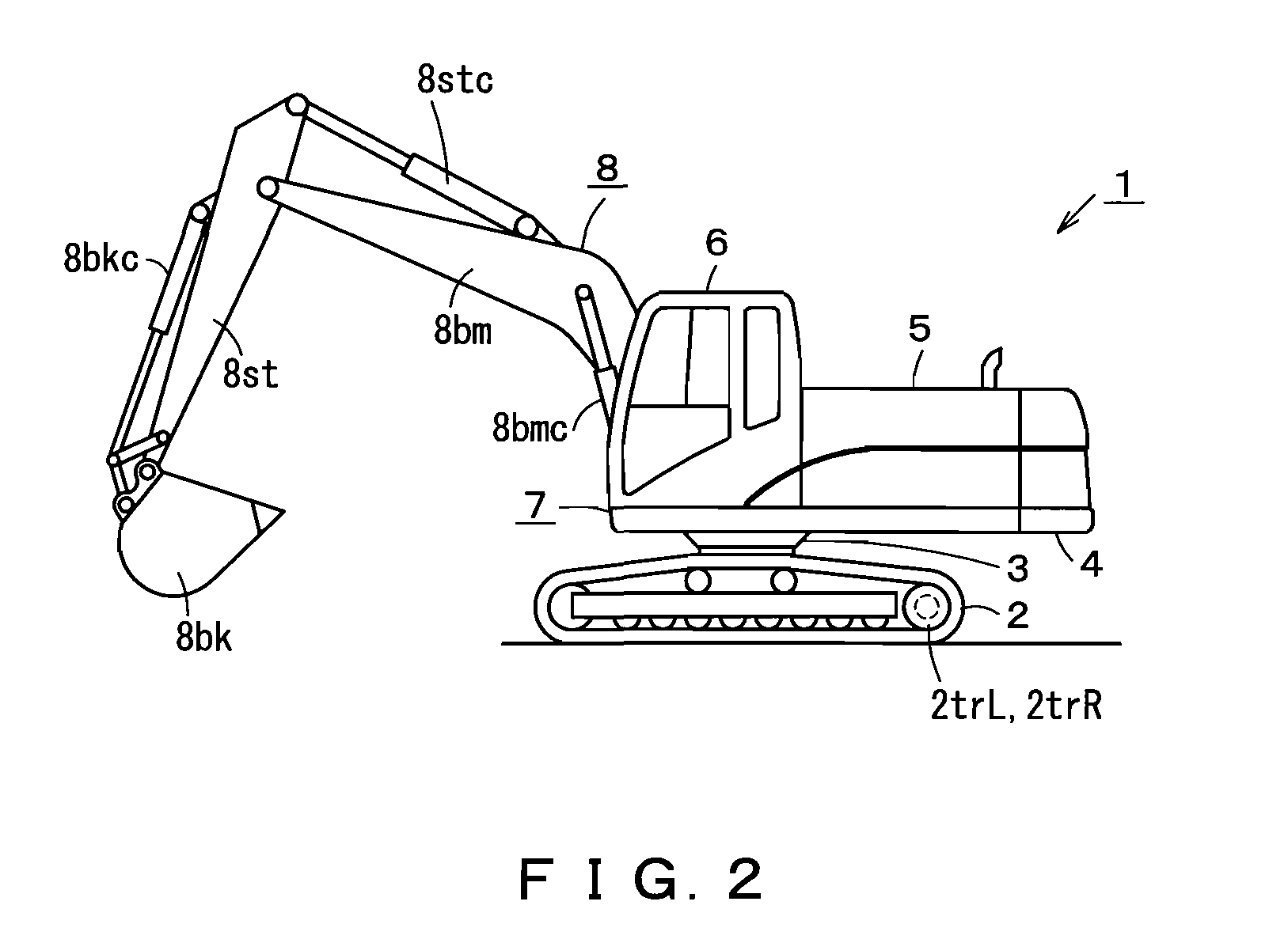
[0023]As shown in FIG. 2, a work machine 1 is a hydraulic excavator that includes a machine body7. The machine body 7 is comprised of a lower structure 2, an upper structure 4 rotatably mounted on the lower structure 2 with a swing bearing portion 3 therebetween, and components mounted on the upper structure 4. The components mounted on the upper structure 4 include a power unit 5 comprised of an engine, hydraulic pumps, etc., and a cab 6 for protecting an operator. The lower structure 2 is provided with travel motors 2trL, 2trR that serve as hydraulic actuators for respectively driving right and left crawler belts. The upper structure 4 is provided with a motor generator (not shown in FIG. 2) for driving a swing deceleration mechanism provided in the swing bearing po...


PUM


Abstract

A swing control circuit is provided separately from a hydraulic actuator control circuit. The swing control circuit includes a swing pump motor connected to closed circuits of a swing motor through a solenoid valve that serves as a directional control valve. A swing motor generator is connected to the swing pump motor. The swing motor generator is connected to an electric power storage device of a hybrid type drive system. An exterior-connecting passage for feeding hydraulic fluid to hydraulic actuators of a lower structure and a work equipment is drawn from a pipeline between the swing pump motor and the solenoid valve. A connecting passage solenoid valve is disposed in the exterior-connecting passage. The invention enables hydraulic energy generated in the swing system to be directly fed to the outside of the swing system.

Description

CROSS REFERENCE TO PRIOR APPLICATION[0001]This is a U.S. national phase application under 35 U.S.C. § 371 of International Patent Application No. PCT / JP2006 / 307534 filed Apr. 10, 2006 and claims the benefit of Japanese Application Nos. 2005-166174 filed Jun. 6, 2005 and 2005-166181 filed Jun. 6, 2005, all of which are incorporated by reference herein. The International Application was published in Japanese on Dec. 14, 2006 as WO 2006 / 132031 al under PCT article 21(2).TECHNICAL FIELD[0002]The present invention relates to a swing drive device provided with a swing motor adapted to drive a load for performing swinging operation by receiving hydraulic fluid. The present invention also relates to a work machine of which an upper structure is adapted to be rotated on a lower structure by such a swing drive device.BACKGROUND[0003]When using a hybrid type drive device in a work machine, such as a hydraulic excavator, it is a common practice to use an electric motor as a swing actuator for r...

Claims


Application Information

Patent Timeline
IPC IPC(8): F15B1/027F15B13/06F15B11/17
CPCE02F9/2075E02F9/2217E02F9/2242E02F9/2292E02F9/2296F15B11/17F15B21/14F15B2211/20515F15B2211/20523F15B2211/20538F15B2211/20546F15B2211/20576F15B2211/3111F15B2211/327F15B2211/63F15B2211/7053F15B2211/7058F15B2211/88
Inventor TOZAWA, SHOJIBINNAKA, MADOKAFURUTA, HIDETO
Owner CATEPILLAR SARL
Why Eureka
Try Eureka