Unlimited stroke drive oil well pumping system

a technology of oil well pumping system and limited stroke, which is applied in the direction of piston pump, fluid coupling, borehole/well accessories, etc., can solve the problem that the walking beam pumping system cannot run at a slow enough rate, and achieve the effect of reducing the rate of fluid flow, efficient and effective movement of formation fluid, and more efficient actuation of the bottom hole pump

Active Publication Date: 2008-12-25
HENRY RES & DEV +1
View PDF6 Cites 88 Cited by
  • Summary
  • Abstract
  • Description
  • Claims
  • Application Information

AI Technical Summary

Benefits of technology

[0006]Another aspect of the present invention is an improved reciprocated pump positioned at the lower end of a string of tubing supported in a borehole, the tubing providing a passageway for moving formation fluid to the earth's surface.
[0008]The pump barrel has an intermediate vent port between the upper and lower ends, the vent port providing a second passageway by which formation fluid enters the barrel.
[0009]A tubular plunger is reciprocated within the barrel. The plunger has an upper and a lower end. A traveling valve controls fluid flow through the tubular plunger.
[0019]Another important advantage of the present invention is the provision of a unique system for adjusting the length of the sucker rod string for more efficient actuation of the bottom hole pump.
[0021]The pump system includes a pump barrel positioned in the borehole having an upper and a lower end. The upper end of the pump barrel is in communication with the tubing. A standing valve is positioned adjacent the lower end of the pump barrel and provides a first passageway through which formation fluid flows into the barrel.
[0024]A plurality of individual non-metallic seal rings, separated by metallic spacers, are positioned on the plunger. The non-metallic seal rings engage the interior cylindrical surface of the pump barrel and are configured to support in substantially leak proof manner the column of formation fluid within the tubing extending to the earth's surface. The non-metallic seal rings and metallic spacers in sealed relationship with the interior surface of the pump barrel provide a system that substantially isolates the portion of the barrel below the seal rings from the tubing pressure there above to thereby allow formation fluid to more freely flow into the lower portion of the pump barrel. That is, by the use of packing fully supporting the weight of the produced fluid contained within the tubing extending from the pump barrel to the earth's surface, the area below the packing is thereby substantially at the formation fluid pressure so that no fluid pressure exists within the pump barrel to reduce the rate of fluid flow from the formation into the barrel. In this way the pump barrel more rapidly fills on each stroke of the plunger to more efficiently and effectively move formation fluid to the earth's surface as the plunger is reciprocated.

Problems solved by technology

In many wells, and stripper wells in particular, the walking beam pumping system cannot run at a slow enough rate.

Method used


Image

  • Unlimited stroke drive oil well pumping system
  • Unlimited stroke drive oil well pumping system
  • Unlimited stroke drive oil well pumping system

Examples


Embodiment Construction

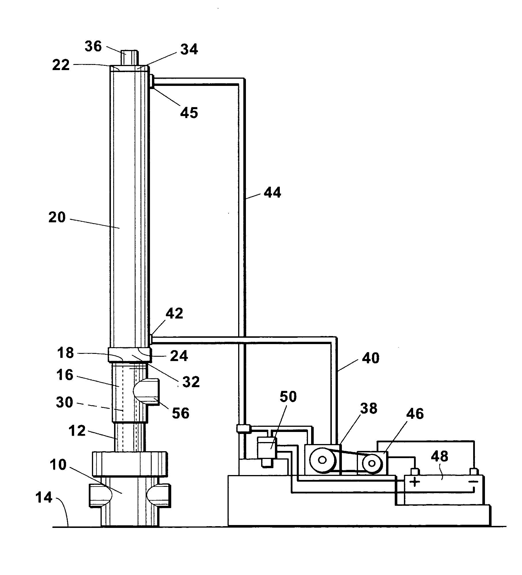
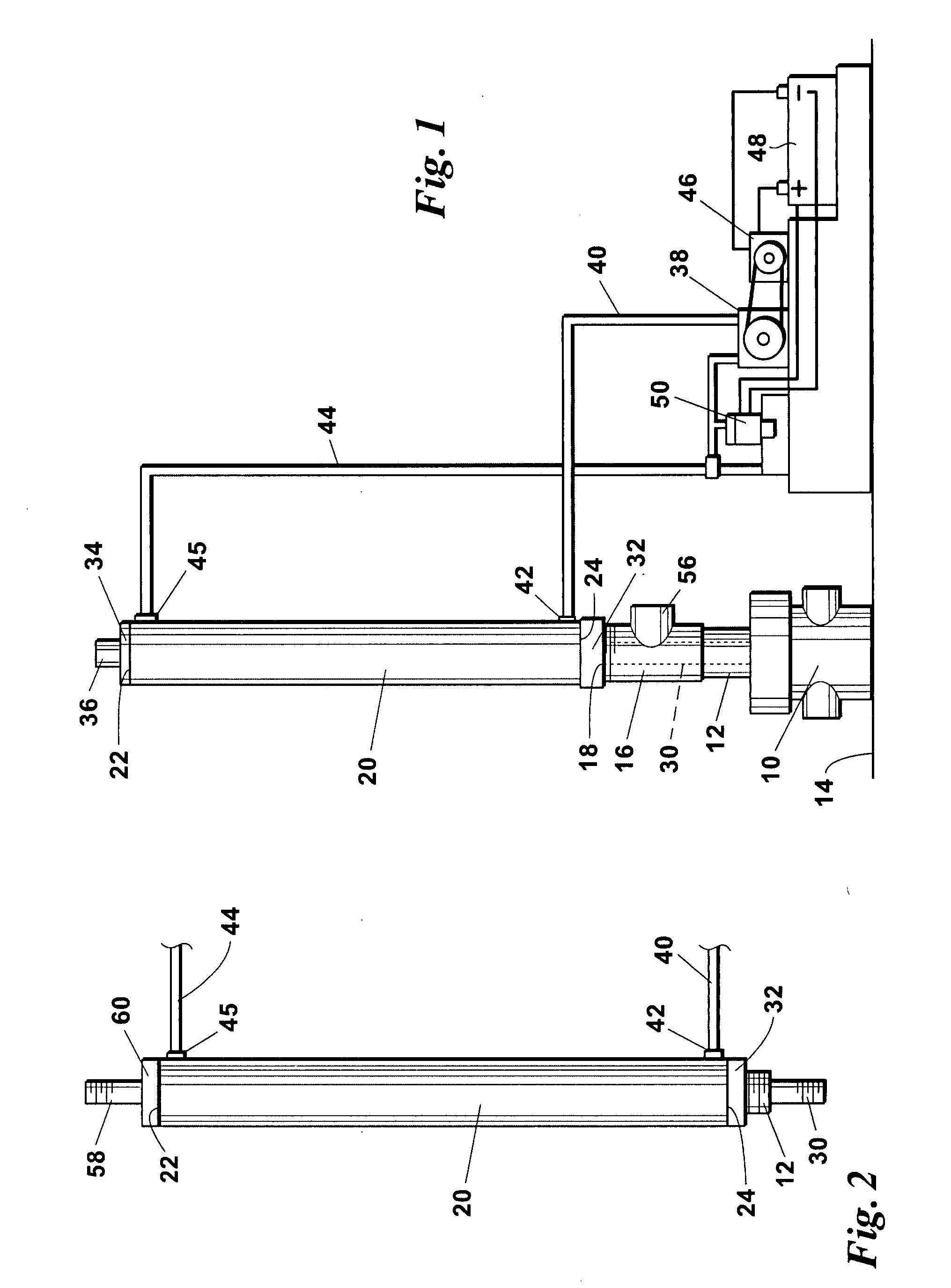
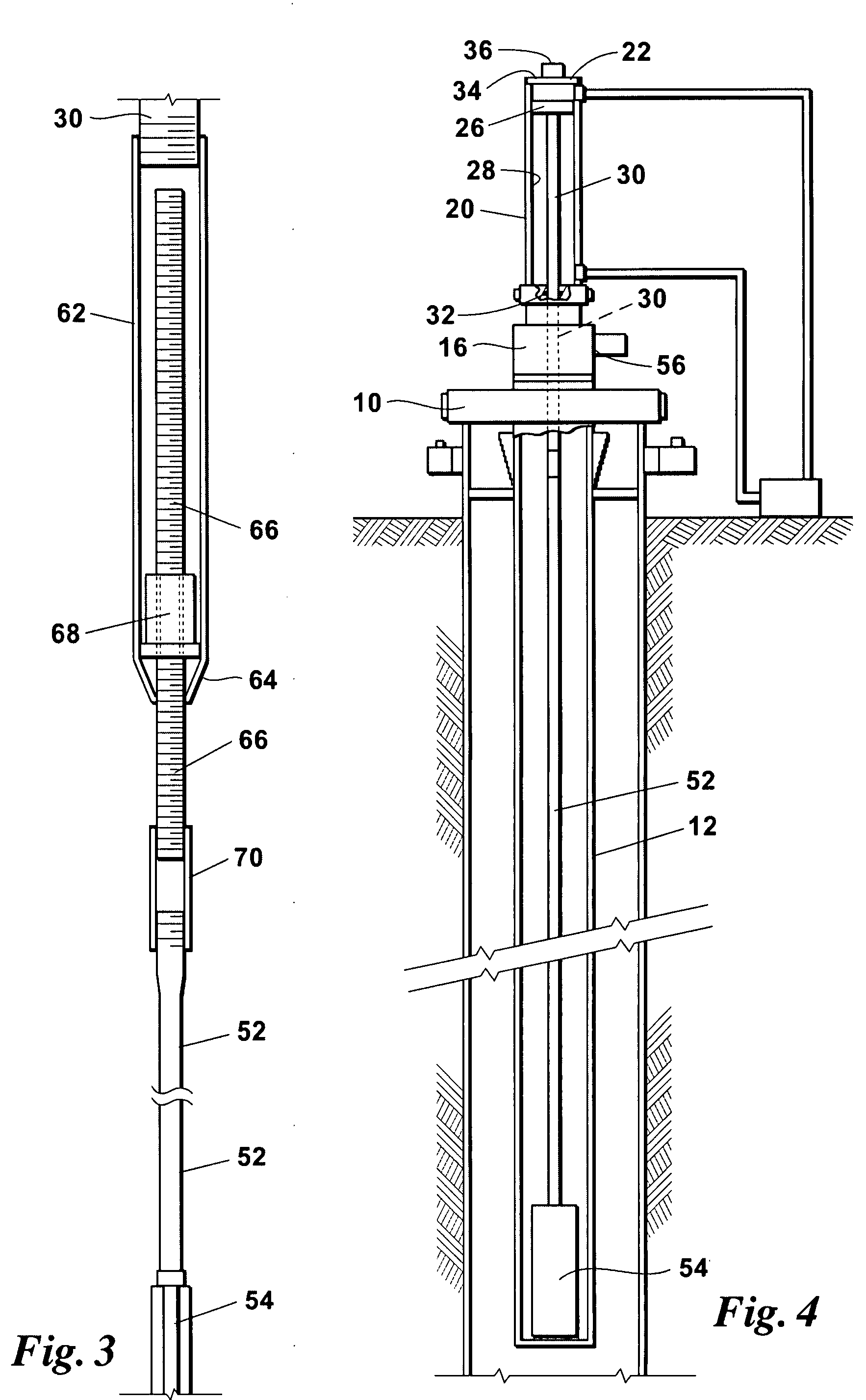
[0052]It is to be understood that the invention that is now to be described is not limited in its application to the details of the construction and arrangement of the parts illustrated in the accompanying drawings. The invention is capable of other embodiments and of being practiced or carried out in a variety of ways. The phraseology and terminology employed herein are for purposes of description and not limitation.

[0053]Elements shown by the drawings are identified by the following numbers:[0054]10 wellhead 74 lower end[0055]12 tubing 76 standing valve[0056]14 earth's surface 78 straining nipple[0057]16 Tee fitting 80 seating shoe[0058]18 top of 1682 casing[0059]20 hydraulic cylinder 84 borehole[0060]22 top end 86 closed chamber[0061]24 bottom end 88 perforations in the tubing[0062]26 piston 90 perforations in the casing[0063]28 internal cylinder wall 92 plunger[0064]30 downward extending piston rod 94 center tube[0065]32 seal member 96 connecting tube[0066]34 closure member 98 c...


PUM


Abstract

An unlimited stroke drive method for pumping fluid from an oil well in which the well has a tubing string extending from the earth's surface down to a fluid producing formation. The method includes the steps of positioning a pump barrel within the tubing, an upper end of the pump barrel having communication through a standing valve with the interior of the tubing string, vertically reciprocating a length of flexible cable within the tubing string to vertically reciprocate a plunger within the pump barrel to allow a lower portion to quickly fill with fluid from the producing formation and then to a downward position in which fluid within the pump barrel lower portion is transferred through a traveling valve to an area within the pump barrel above the plunger to move formation fluid from within the pump barrel to the interior of the tubing and thence to the earth's surface.

Description

REFERENCE TO PENDING APPLICATIONS[0001]This application is a continuation-in-part application which claims priority to U.S. patent application Ser. No. 11 / 668,252, filed on Jan. 29, 2007 and entitled “An Improved Reciprocating Pump System For Use In Oil Wells” which in turn is a continuation-in-part application which claims priority to U.S. patent application Ser. No. 11 / 103,067, filed on Apr. 11, 2005, and entitled “Improved Hydraulic Pump Jack System For Reciprocating Oil Well Sucker Rods”.FIELD OF THE INVENTION[0002]This invention relates to an unlimited stroke drive oil well pumping system for reciprocating an oil well pump located in the bottom portion of a string of tubing in which the pump is reciprocated by a flexible cable extending from the pump to the earth's surface, and an improved rapid fill pump for use in the system.BACKGROUND OF THE INVENTION[0003]Oil wells typically vary in depth from a few hundred feet to several thousand feet. In many wells there is insufficient ...

Claims


Application Information

Patent Timeline
Patent Type & Authority Applications(United States)
IPC IPC(8): F04B27/04E21B43/00
CPCE21B43/127F04B47/04E21B43/126
Inventor BROWN, T. LEON
Owner HENRY RES & DEV
Why Eureka
Try Eureka