Coil apparatus and magnetic resonance imaging apparatus using the same

a coil apparatus and magnetic resonance imaging technology, applied in the direction of magnetic measurements, instruments, measurement devices, etc., can solve the problems of inapplicability, complex circuit adjustment, and the degree of uniformity of effective sensitivity decreases, and achieves simple configuration and uniform sensitivity.

Inactive Publication Date: 2008-12-25
HITACHI LTD
View PDF13 Cites 8 Cited by
  • Summary
  • Abstract
  • Description
  • Claims
  • Application Information

AI Technical Summary

Benefits of technology

[0021]The present invention provides a coil apparatus which causes one coil to have a uniform sensitivity region and tune two frequencies. This allows the same coil in the MRI apparatus to detect NMR signals from two types of nucleus and realizes measurement of different types without moving the inspection target.
[0022]Furthermore, the coil apparatus of the present invention provides electromagnetic wave penetrability between the plurality of linear conductors arranged neighboring each other so as to allow an RF magnetic field to enter from outside. Therefore,...

Problems solved by technology

However, the method described in Patent Document 1 assigns rungs arranged in a circumferential direction to every other different frequency in the circumferential direction, and the method therefore has a disadvantage that the degree of uniformity in effective sensitivity decreases.
On the other hand, the method described in Patent Document 2 involves problems that adjustment of the circuit is complicated and the capac...

Method used


Image

  • Coil apparatus and magnetic resonance imaging apparatus using the same
  • Coil apparatus and magnetic resonance imaging apparatus using the same
  • Coil apparatus and magnetic resonance imaging apparatus using the same

Examples


first embodiment

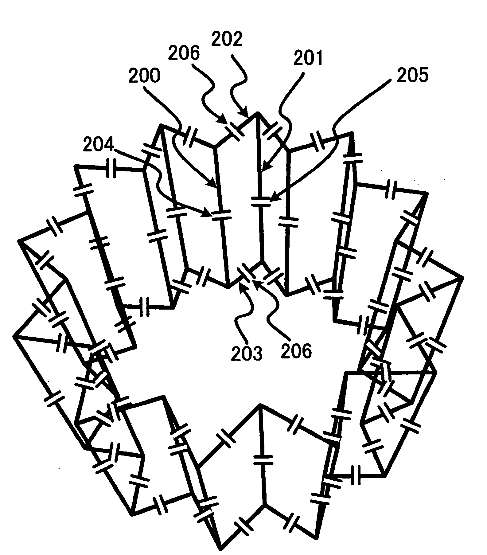
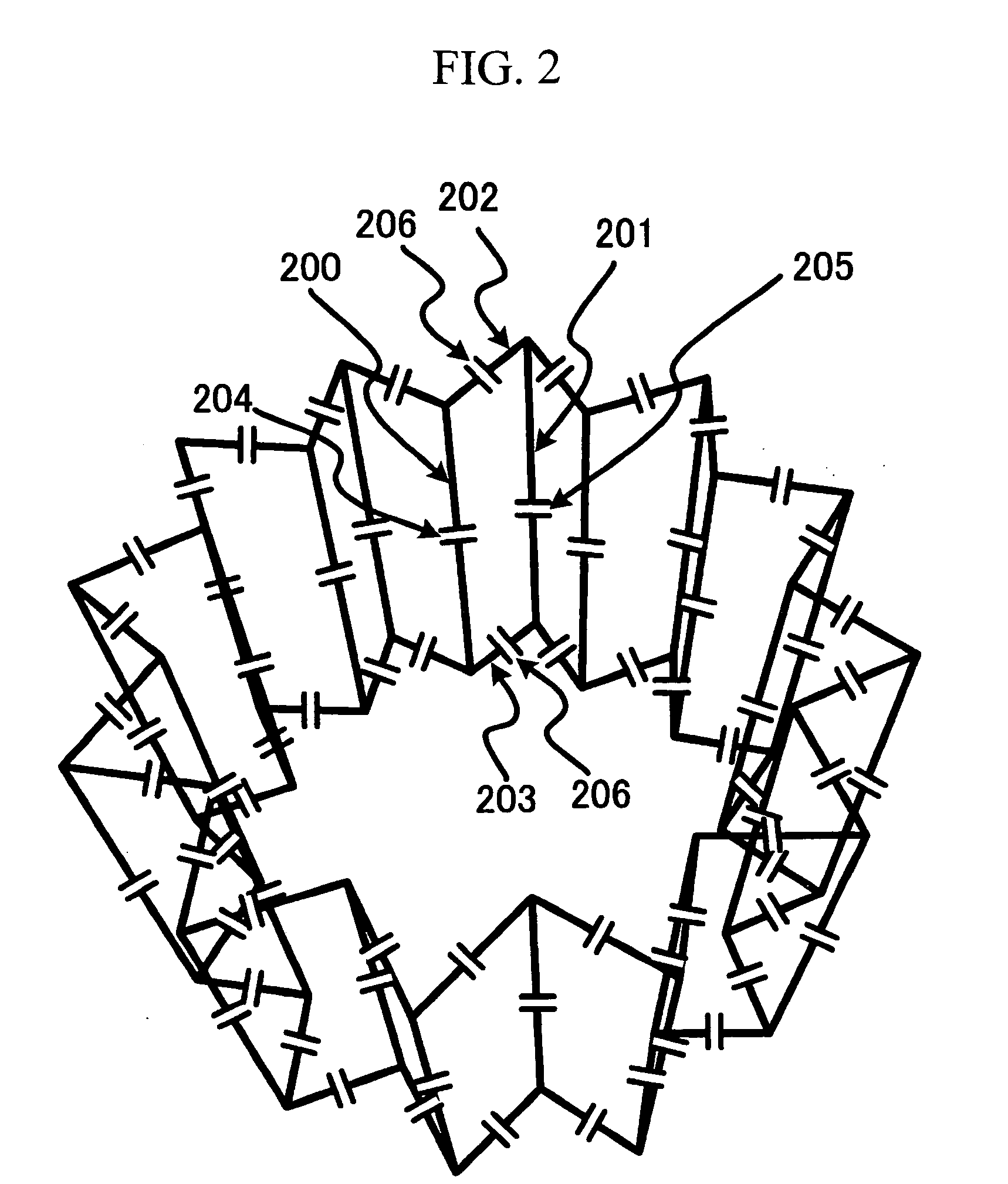
[0050]FIG. 2 shows an overall view of a first embodiment of the coil apparatus of the present invention. This coil apparatus is an RF coil suitable, for example, for a coil for the head of a horizontal magnetic field MRI.

[0051]The RF coil of this embodiment is constructed of a plurality of linear conductors 200, 201, first conductors 202 connected to one ends of these linear conductors 200, 201, second conductors 203 connected to the other ends of the linear conductors 200, 201, capacitors 204, 205 inserted in the linear conductors 200, 201 and capacitors 206 inserted in the first conductors 202 and second conductors 203, and has a cylindrical structure as a whole. The power supply circuit and / or power receiving circuit is omitted in FIG. 2, but the power supply circuit and / or power receiving circuit are added in parallel with any one of the capacitors 204 to 206.

[0052]The figure shows the case where the number of linear conductors is 24, but the number of linear conductors is not l...

second embodiment

[0075]FIG. 10 shows a coil apparatus according to a second embodiment. This coil apparatus is different in that capacitors 206 exist only on upper and lower sides of star ring conductors and no capacitor is provided for a plurality of linear conductors. In this case, since a combined capacitance is determined only by the capacitance of the capacitors 206, the degree of freedom in setting two resonance frequencies is decreased. As shown in FIG. 7, the impedance characteristic of the coil apparatus according to the first embodiment is such that a peak in the birdcage type resonance mode appears on the low frequency side and a peak in the multiple patch resonator type mode appears on the high frequency side, but on the contrary, according to this embodiment, a birdcage type resonance mode appears on the high frequency side, while a resonance mode having sensitivity nodes in the vicinity of the circumference of the first radius appears on the low frequency side. The frequency characteri...

third embodiment

[0077]The coil apparatus shown in FIG. 11 is different only in that capacitors 204, 205 exist only on a plurality of linear conductors and no capacitor is provided for ring parts. The combined capacitance is also determined only by the capacitances of the capacitors 204, 205 in this case, and therefore the degree of freedom in setting two resonance frequencies decreases. In the impedance characteristic of this coil apparatus, as in the case of the first embodiment, a peak in a birdcage type resonance mode appears on the low frequency side and a peak in a multiple patch resonator type mode appears on the high frequency side. The frequency characteristic in the birdcage type resonance mode is of a low pass type and the birdcage type mode is suitable for detection of a signal having a relatively low resonance frequency.

[0078]Though the coil apparatus of this embodiment has a low degree of freedom in setting two frequencies, it is better than the first embodiment in that the number of p...


PUM


Abstract

There is provided an RF coil capable of resonating or tuning two frequencies, having uniform spatial sensitivity and having a small spatially occupied volume, especially an RF coil suitable for a high magnetic field MRI apparatus. A coil apparatus is made up of a plurality of linear conductors 200, 201 arranged around a central axis and two ring conductors 202, 203 connected to the respective ends of the plurality of linear conductors 200, 201 and capacitors are inserted in the linear conductors 200, 201 and ring conductors 202, 203. The plurality of linear conductors are made up of conductors 200 located near the central axis and conductors 201 located far from the central axis and the ring conductors 202, 203 have star-like polygonal shape so that the linear conductors are arranged alternately. This structure can realize two tuning modes; a resonance mode similar to a birdcage type resonance mode and a resonance mode which becomes zero (node) in the vicinity of the linear conductor group 200 located near the central axis.

Description

CLAIM OF PRIORITY[0001]The present application claims priority from Japanese application JP 2007-113252 filed on Apr. 23, 2007, the content of which is hereby incorporated by reference into this application.BACKGROUND OF THE INVENTION[0002]1. Field of the Invention[0003]The present invention relates to a coil apparatus for transmitting / receiving electromagnetic waves and a magnetic resonance imaging apparatus using the same (hereinafter referred to as “MRI apparatus”).[0004]2. Background Art[0005]MRI apparatuses are designed to irradiate an examinee placed in a uniform static magnetic field produced by a magnet with an electromagnetic field, excite nuclear spin in the examinee's body, then receive a nuclear magnetic resonance signal which is electromagnetic wave produced by the nuclear spin and image the examinee. Irradiation of the electromagnetic wave and reception of the nuclear magnetic resonance signal are realized by an RF coil which transmits or receives radio frequency (RF) ...

Claims


Application Information

Patent Timeline
IPC IPC(8): G01R33/341
CPCG01R33/34007G01R33/34076G01R33/3635
Inventor HABARA, HIDETABITO, YOSHITAKASOUTOME, YOSHIHISAOCHI, HISAAKI
Owner HITACHI LTD
Why Eureka
Try Eureka