Light Quantity Adjustment Method, Image Recording Method, and Device

a technology of light quantity and adjustment method, applied in the direction of circuit masks, instruments, printing, etc., can solve the problems of inability to make correct adjustments, image recorded on photosensitive materials suffer irregularities, and cannot guarantee that images free of irregularities will be recorded. , to achieve the effect of recording a desired image highly accurately

Inactive Publication Date: 2008-12-25
FUJIFILM CORP
View PDF4 Cites 20 Cited by
  • Summary
  • Abstract
  • Description
  • Claims
  • Application Information

AI Technical Summary

Benefits of technology

[0006]It is a general object of the present invention to provide an amount-of-light adjusting method, an image recording method, and an image recording apparatus which are capable of recording a desired image free of irregularities highly accurately on an image recording medium using a plurality of light sources.
[0007]A major object of the present invention is to provide an amount-of-light adjusting method, an image recording method, and an image recording apparatus which are capable of recording a desired image highly accurately by correcting localities of the amounts of light of light beams emitted from respective light sources.
[0008]Another object of the present invention is to provide an amount-of-light adjusting method, an image recording method, and an image recording apparatus which are capable of recording a desired image highly accurately by correcting irregularities caused by process in an image recording medium.
[0009]A further object of the present invention is to provide an amount-of-light adjusting method, an image recording method, and an image recording apparatus which are capable of recording a desired image highly accurately by correcting irregularities caused by sensitivity characteristics of an image recording medium.

Problems solved by technology

If the amounts of light of the light beams emitted from the light sources differ from each other, then an image recorded on the photosensitive material suffers irregularities.
However, since the photodetectors generally have different sensitivities with respect to wavelengths of light detected thereby, if the light beams emitted from the respective light sources have different wavelengths, then detected values of the amounts of light are also different from each other, failing to make correct adjustment.
Consequently, even if the amounts of light of the light beams are adjusted in view of the wavelength dependency of the photodetectors, there is no guarantee that images free of irregularities will necessarily be recorded.
If the light beams have different beam diameters and are focused differently by an optical system, then the recorded image will suffer irregularities even when the image is recorded with the same amounts of light of the light beams.

Method used


Image

  • Light Quantity Adjustment Method, Image Recording Method, and Device
  • Light Quantity Adjustment Method, Image Recording Method, and Device
  • Light Quantity Adjustment Method, Image Recording Method, and Device

Examples


Embodiment Construction

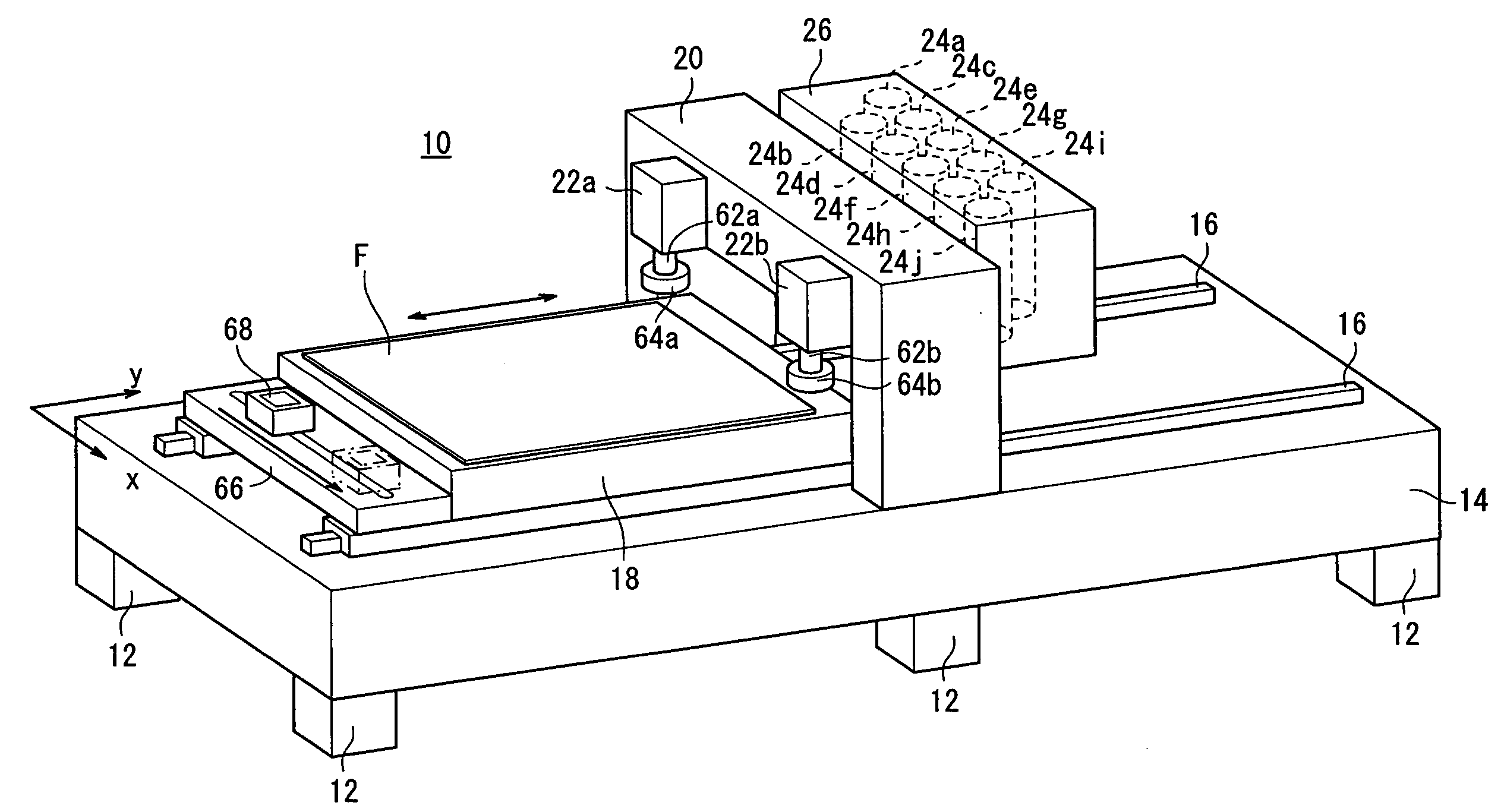
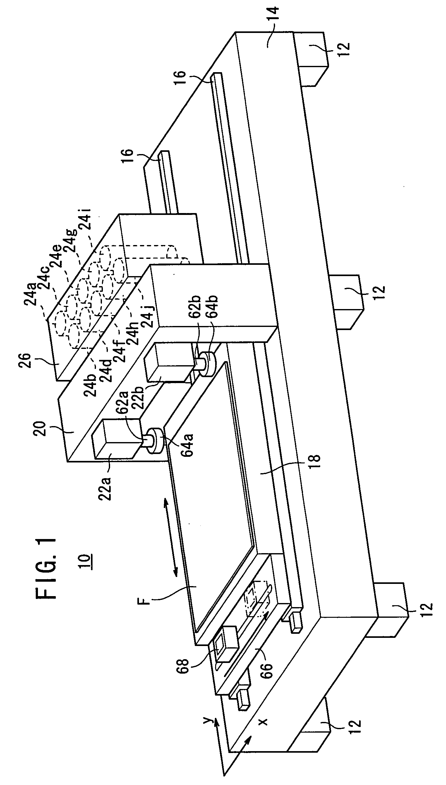
[0037]FIG. 1 shows an exposure apparatus 10 for performing an exposure process on a printed wiring board, etc., to which an amount-of-light adjusting method, an image recording method, and an image recording apparatus according to an embodiment of the present invention are applied. The exposure apparatus 10 has a bed 14, which suffers very little deformations, supported by a plurality of legs 12, and an exposure stage 18 mounted on the bed 14 by two guide rails 16 for reciprocating movement in the directions indicated by the arrow. An elongate rectangular substrate F (mage recording medium) coated with a photosensitive material is attracted to and held on the exposure stage 18.

[0038]A portal column 20 is mounted centrally on the bed 14 over the guide rails 16. Two CCD cameras 22a, 22b are fixed to one side of the column 20 for detecting the position in which the substrate F is mounted with respect to the exposure stage 18. A scanner 26 having a plurality of exposure heads 24a throug...


PUM


Abstract

According to test data supplied from a test data memory (80), a test pattern is formed on a substrate (F) and its line width is measured. Light source units (28a to 28j) are adjusted by a light source control unit (89) and the line width change amount between exposure heads (24a to 24j) is corrected so as to set the obtained light quantity. In a mask data setting unit (86), mask data is set so as to control a particular micro mirror of DMD constituting the exposure heads (24a to 24j) to OFF state. By using the mask data, the output data is corrected and a desired image is exposed/recorded on a substrate (F).

Description

TECHNICAL FIELD[0001]The present invention relates to an amount-of-light (light quantity) adjusting method, an image recording method, and an image recording apparatus (device) for controlling a plurality of exposure heads having independent light sources for outputting light beams and arrayed along an image recording medium, depending on image data, to record an image on the image recording medium.BACKGROUND ART[0002]FIG. 27 is a view illustrative of a process of manufacturing a printed wiring board. A substrate 2 with a copper foil 1 deposited thereon by evaporation or the like is prepared. A photoresist 3 made of a photosensitive material is pressed with heat against (laminated on) the copper foil 1. After the photoresist 3 is exposed to light according to a wiring pattern by an exposure apparatus, the photoresist 3 is developed by a developing solution. Then, the portion of the photoresist 3 which has not been exposed is removed. The copper foil 1 that is exposed by the removal ...

Claims


Application Information

Patent Timeline
Patent Type & Authority Applications(United States)
IPC IPC(8): G03B27/72
CPCB41J2/465G03F7/7005G03F7/70283G03F7/70291G03F7/70558G03F7/70625H05K1/0269H05K3/0082H05K3/064H05K2201/09781H05K2203/163
Inventor SUMI, KATSUTOSUZUKI, ISSEIKOWADA, KAZUTERU
Owner FUJIFILM CORP
Why Eureka
Try Eureka