
Compact Super Wide-Angle Imaging System

a super wide-angle imaging and compact technology, applied in the field of wide-angle optical imaging systems, can solve the problems of long total track length, severe distortion of illumination, etc., and achieve the effect of short lens design

Active Publication Date: 2008-12-25
RICOH KK
View PDF10 Cites 21 Cited by
  • Summary
  • Abstract
  • Description
  • Claims
  • Application Information

AI Technical Summary

Benefits of technology

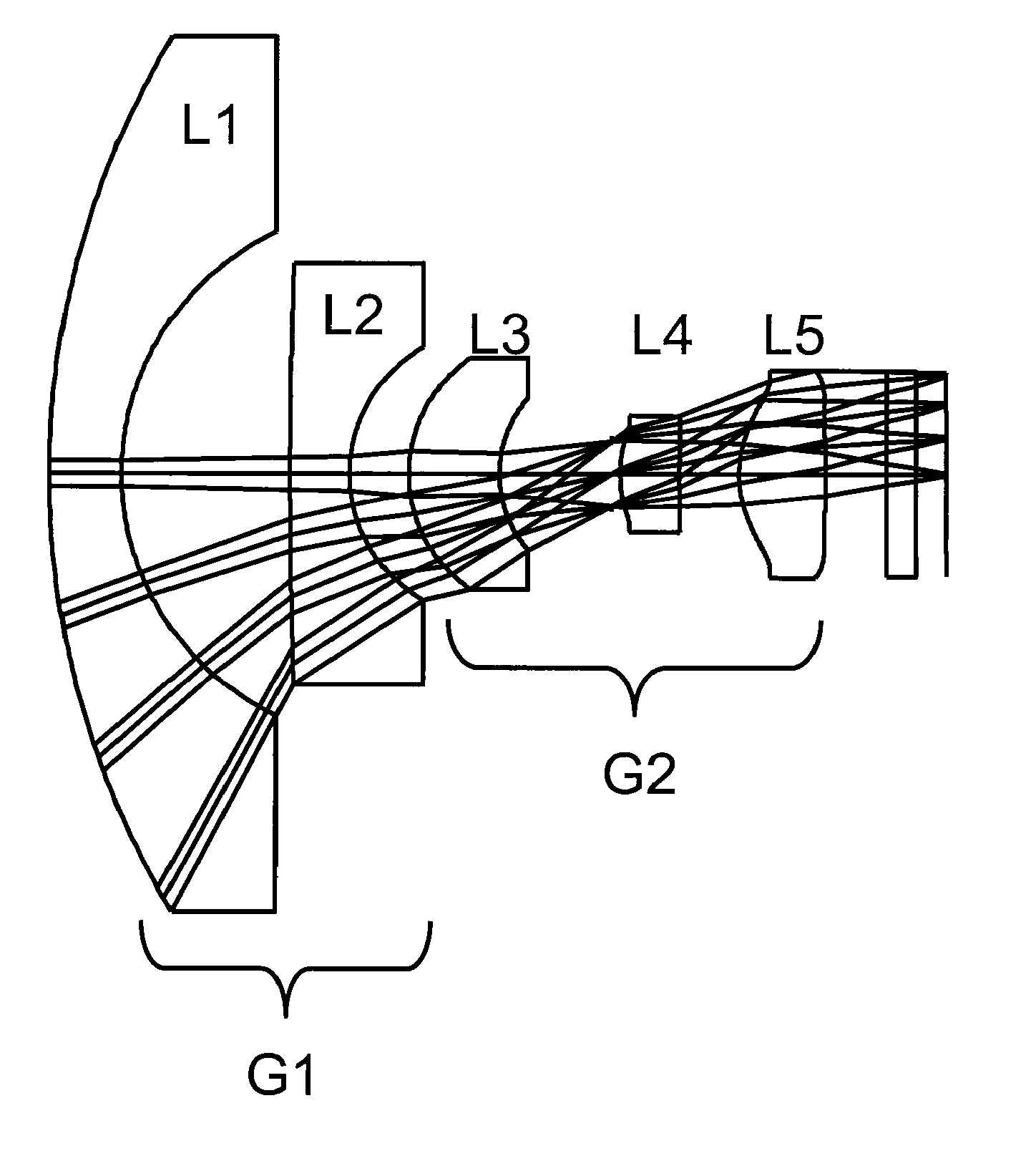
The present invention provides a super wide-angle imaging system with a short total track length. The optical portion of the system is a retrofocus type lens system with a first lens group and a second lens group. The first lens group acts to bend the wide field angles into smaller field angles and extend the back focal distance while preserving a small effective focal length. The second lens group acts to correct optical aberrations and direct the flux onto the photodetector array at the image plane. The imaging system includes subsequent digital processing to compensate for otherwise unacceptable aberrations introduced by the compact optical system. The lens system can be designed with a short total track length using only a few lens elements without any cemented lens elements. The lens system can be designed to compensate for other aberrations, such as axial defocus aberration, by using strong spherical aberration. The invention also includes systems that incorporate the imaging systems described above and applications for these systems.

Problems solved by technology

Previous designs for optical systems have satisfied some of these requirements, but not all of them.
Some designs require only a few easy-to-manufacture lens elements, but require long total track lengths.
Others shorten the total track length but require many lens elements and often suffer from illumination fall-off or severe distortion.

Method used


Image

  • Compact Super Wide-Angle Imaging System
  • Compact Super Wide-Angle Imaging System
  • Compact Super Wide-Angle Imaging System

Examples


example one

[0029 Design.

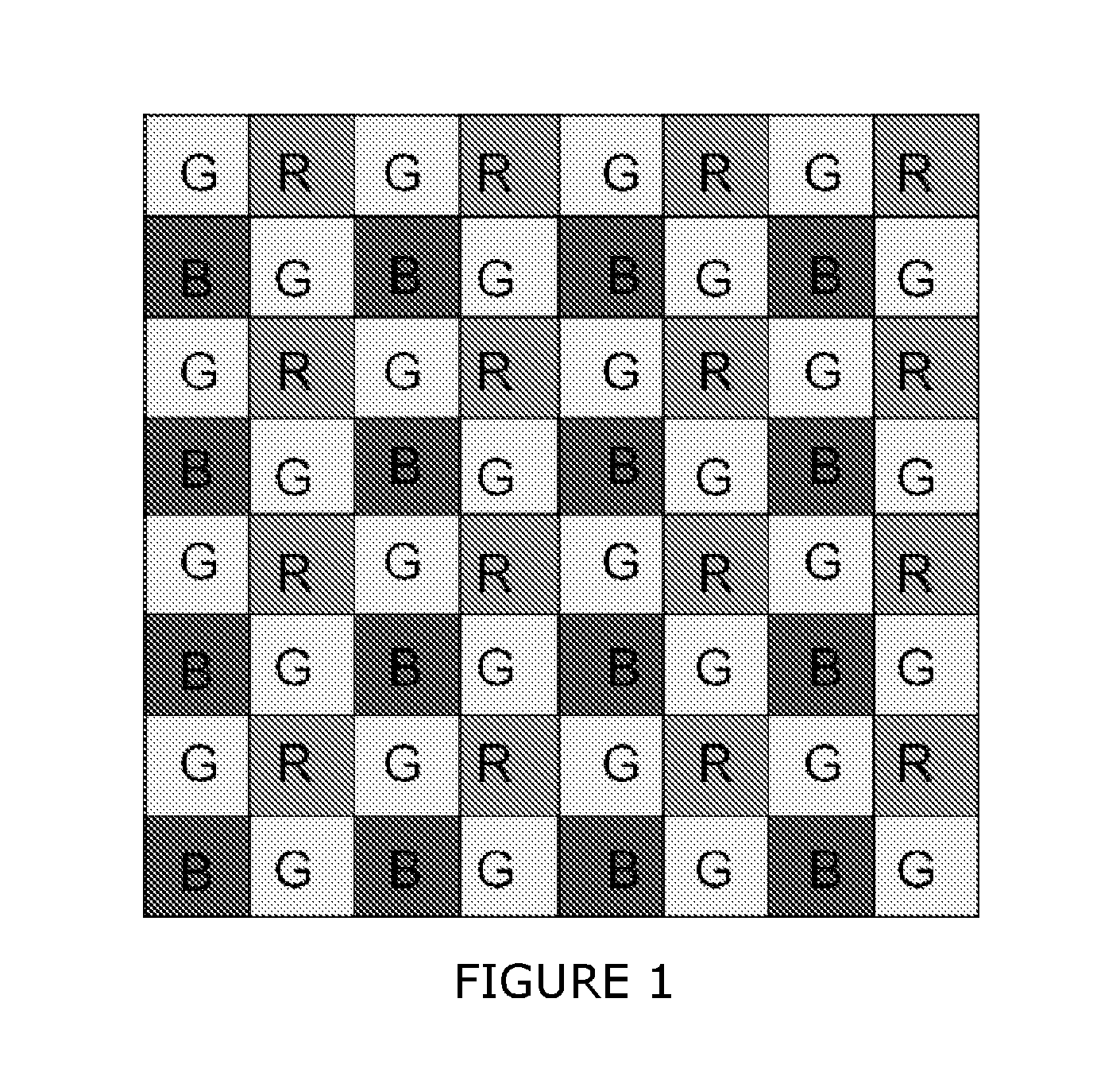
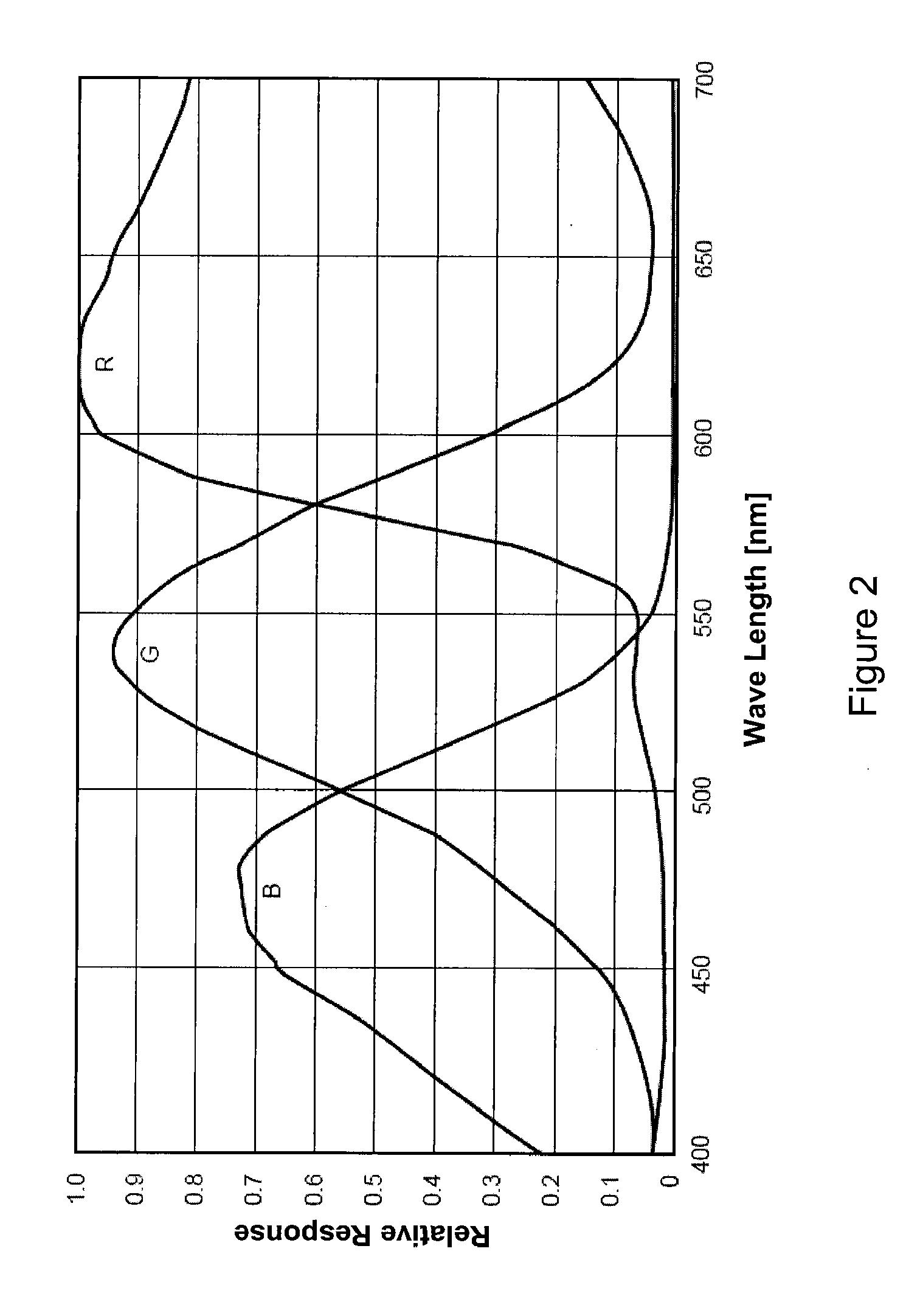
[0030]FIG. 3 shows a compact five-lens optical system according to the invention. The lens design has a focal length of f=0.8 mm with a 190 degree field-of-view. The lens is an F / 2.8 lens with a maximum field height of 1.71 mm, corresponding to a 1 / 7 inch VGA resolution image sensor having 4.25 μm pixels. The system is designed for three-color operation over the spectral range of 425-700 nm, using a standard Bayer pattern for the color filters.

[0031]The optical prescription for the lens design is shown in Table 1. The fourth and fifth lenses are aspheres. The aspheric terms are defined by the conic constant k and the rotationally symmetric higher order even polynomial terms. The aspheric surface is defined by the rotationally symmetric surface with surface sag S(ρ) as a function of radial distance ρ defined by

S(ρ)=ρ2R1+1-(1+k)p2R2+c4p4+c6p6+c8p8+c10p10(1)

where R is the radius of curvature of the surface. Table 1 also gives the values for the aspheric terms.

TABLE 1Exampl...

example two

[0049 Design.

[0050]FIG. 9 shows a compact four-lens optical system according to the invention. The lens design has a focal length of f=1.12 mm with a 190 degree field-of-view. The lens is an F / 2.6 lens with a maximum field height of 1.71 mm corresponding to a 1 / 7 inch VGA resolution image sensor having 4.25 μm pixels. The system is designed for three-color operation over the spectral range of 425-700 nm, using a standard Bayer pattern for the color filters.

[0051]The optical prescription for the lens design is shown in Table 3. This design is a more extreme version of the axial and lateral chromatic aberration relaxation described in the previous example. The lens system includes a first negatively powered lens group G1 and a second positively powered lens group G2. The third and fourth lenses are aspheric elements. The aspheric terms are defined by the conic constant k, the rotationally symmetric higher order even polynomial terms and some non-rotationally symmetric polynomial terms...


PUM


Abstract

A super wide-angle imaging system has a short total track length. The lens system is a retrofocus type lens system that uses only a few lenses with no cemented lens elements. Acceptable performance is achieved by taking advantage of subsequent digital image processing. The compact lens system is designed to create optical images that can be restored by subsequent digital processing that compensates for otherwise unacceptable aberrations introduced by the lens system.

Description

BACKGROUND OF THE INVENTION[0001]1. Field of the Invention[0002]This invention relates generally to wide angle optical imaging systems, including such systems that are suitable for use on motor vehicles.[0003]2. Description of the Related Art[0004]Manufacturers of motor vehicles are increasingly equipping their vehicles with imaging systems. For example, manufacturers are installing imaging systems at the rear of the vehicle to assist drivers when the vehicle is backing up. To increase the visibility for drivers and potentially eliminate blind spots altogether, these imaging systems preferably have a very wide field of view. Fields of view between 160-200 degrees (at least along the horizontal direction) are desirable to fully capture the scene at the rear of a vehicle. In addition to rear-looking systems, vehicular mounted imaging systems can also be used for other purposes, for example to detect lane markers or other guidance markings, to allow the driver to view directions other ...

Claims


Application Information

Patent Timeline
Patent Type & Authority Applications(United States)
IPC IPC(8): G02B13/18
CPCG02B13/06G02B27/0025
Inventor ROBINSON, M. DIRK
Owner RICOH KK
Learn More